• Untitled Document

    Join us on April 26th, 7pm EST

    for the CBEC Virtual Meeting

    All EYO members and followers are welcome to join the fun and get to know the guest speaker!

    See the link below for login credentials and join us!

    April Meeting Info

    (dismiss this notice by hitting 'X', upper right)

M25xp, convert from 3 point mount to 4?

Loren Beach

O34 - Portland, OR
Senior Moderator
Blogs Author
Those big molded-in rails (i.e. "bed logs") on our model are both hollow, but seem to have a piece of hardwood in the top part.
I would guess that they are at least 1/4 inch thick. It's a heavy layup.
Unlike the BK Ericson's, our boat was engineered with the four point engine mounting.
FWIW, it does take some careful alignment to get (most of) the vibration out. No magic answers here.... :rolleyes:

Loren
 

EGregerson

Member III
In defense of lag screws

in poking around the net re: mounts etc; i see a number of sites with people having similar issues; only with lag screw holding 5.7L motors? Magnum 454's? wow. it's to soon to say this is an industry standard; but certainly appears lags are commonplace. Regarding bigd14 options, I like Scenario 2; it looks stable. I'm really thinking of plugging the (lag) holes with epoxy and a machine screw (coated with pam!); that seems like a good way to lock down the mounts without having to drill access holes to feed in a nut and water underneath.
 

bigd14

Contributing Partner
Blogs Author
Frank, I am not sure yet about the wood under the stringers. I will do some exploratory drilling next time I'm at the boat. I suspect that there is wood. EGregerson, good point about the lags on larger engines. I agree a threaded hole seems better, but I guess it depends on how much depth you can get.
 
Last edited:

Ian S

Member III
I think it needs to be stated that the typical problem with lag screws is that many have a long unthreaded section of shank. These types should be avoided as the section of thread holds little because as I believe Loren indicated after approximately a 1/4" of glass and another 3/4" or so of plywood you have a hollow structure. A slightly finer wood thread will have much more holding power as opposed to a very coarse thread due to surface area and a reduced angle of inclined plane. This is why high load bolts typicaly have fine threads. Personally if I were looking to upgrade from lags I would embed threaded bronze or stainless barrels via thickened epoxy and then bolt down the mounts with machine screws. One could also use a a "riv-nut" of appropriate size from a supplier like McMaster Carr. and bolt the mouth down. I too was suspect of the lags and did have one or two that were seemingly slipping. The solution was wetting the wood out with epoxy for piece of mind. I use a plumbers flux brush for such things. Their cheap, long, and disposable. I think the steel plate to accept the mounts is perhaps more trouble than it's worth. My opinion would also be to ditch the front mount altogether and fabricate two new mounts bolted directly to the block. that front mount keeps both sides linked together and therefor not truly isolated. Think of it like independent suspension vs solid axle. Since some mounts may be longer and thereby subject to greater potential flexing you could always add gussets to stiffen them but probably unecessary. We're really dealing with very light engines and relatively low level forces. I would perhaps mock up the mounts with cardboard and welding rod. Cut some pieces of cardboard the same width as the steel you intend to use, say for example 3/8" x 2-1/2". You could then tape either one or two sections of welding rod (or equiv.) to hold your angles. Just an idea? maybe a plywood mock up? I think we just have to get creative in our approaches.

I would also like to reiterate my love for the iso-flex mounts. The fact that you can replace just the doughnut when worn and or change bushing durometer at will is a huge advantage in my mind. I have eliminated certain harmonics just by changing the doughnut stiffness. The mount itself never goes bad and iso flex uses an aluminum base with a well galvanized stud. Many of the OEM mounts I come across are heavily corroded and were never intended for the marine environment. Iso-flex also uses proprietary plastics and urethanes as opposed to the ancient technology of rubber mounts which crack, dry out, compress and are not really all that immune to solvents and oils like the urethane mounts are. Lastly they manufacture bases which will accommodate most OEM patterns and spacings .http://isoflex.com.au (they should offer me a job! LOL) these are also great for others who are just simply looking to replace worn mounts.

Keep on moving on!
Capt. Ian
 

EGregerson

Member III
call me 'dark cloud'

But i just think these might be too light; 5/16" when if u had ur choice u'd probably go with at least 1/2". Why doesn't McCarr offer these in a larger size; i suspect there is a good reason. This is not where u want to be experimenting; u don't want to be pulling it apart again if it fails. And they're coarse threads; elsewhere on this post someone mentions the enhanced holding power of fine threads; sounds better.
 

Ian S

Member III
Heavy Duty Twist-Resistant Rivet Nuts


A hex-shaped body provides the highest twist resistance of any rivet nut. They're zinc plated for mild corrosion resistance. Install in a drilled hole with a lever-style or power-driven rivet nut tool. The tool collapses the nut, creating a backside flange that holds the nut to the material. Length is measured from under the flange. Installed length is the maximum length of the barrel when installed.


https://www.mcmaster.com/#rivets/=1643m7q

OR

Adhesive-Grip Internally Threaded Anchors for Concrete


Anchors are internally threaded for high pull-out strength in shallow concrete holes as well as where high vibration is present. Fill a clean, drilled hole half full with epoxy adhesive, then insert the anchor until it's flush with the surface. All have Class 2B thread fit. Ultimate pull-out strength is based on tests using epoxy adhesive in 3,000 psi concrete.

https://www.mcmaster.com/#internally-threaded-anchors/=1643o4m
 
Last edited:

bigd14

Contributing Partner
Blogs Author
Frank- There is wood underneath the fiberglass stringers. Not sure what type, but it appears to not go too deep and appears pretty dry and not super solid. Its probably fir or plywood, not a hardwood. At least in the front part (the single mount), there appears to be a hollow underneath, probably the bilge. So trying to fill any holes with epoxy may be futile unless you can use the foam earplug trick, but that may not leave you too much bearing surface above it. EGregerson, I hear you about experimenting with this. I do NOT want it to fail. So I am not sold on the insert. I also need to preserve some adjustment capability which I am not sure I would have with a 1/2" bolt. Capt. Ian, the rivet nuts have to bear on the back surface of the fiberglass stringer, but with wood underneath it that will be impossible. I am going to have to come up with another alternative. Perhaps going back to trying to fit a nut or backer under the stringers and through bolting to that. So I still have some thinking to do.

Thanks for all the advice. Keep the thoughts coming!

Wood Stringer.jpg
 

bgary

Advanced Beginner
Blogs Author
Keep the thoughts coming

I don't have any idea what these things are called, but I have seen "plug" inserts that are threaded radially.

Capture.JPG

You'd drill a hole athwarthships through the engine bed, same diameter as the insert, slide in the insert, thread a bolt into it from the top to hold the alignment, and then epoxy it in place. would be a permanent foundation for the engine-mount bolts, and likely at least as strong as the original lag screws.

You could probably even make something like this... stainless stock of a diameter to suit the space you have, cut to a length that matches the width of the engine bed, then tapped and epoxied in place.

Probably not a great idea, but... thought I'd throw it out there.
 
Last edited:

Ian S

Member III
the mechanical bond of the epoxy to the anchor and to the surrounding area will be stronger that the material surrounding it. I have bedded brass knurled barrels into 3/8" FRP and if you cranked down to hard it would just rip out the fiberglass around it. I think we may be over estimating the forces the mounts will face. With 2 fasteners in each mount, thereby halving each fasteners load and underestimating the strength of a 1/2"+ of FRP particularly with wood backing. In Re. to the riv nut, yes it will not expand on the backside of the material as designed but it will expand and get a good bite, add that to being set with thickened epoxy it will hold a lot of force, I see no need for the hole being plugged as it's of no consequence. We are merely looking to achieve a good bond with the perimeter. thickened epoxy mixed to a proper consistency will not run out of the hole and the fastener may well protrude beyond the barrel anyway.

The only other technique that I have used is to bury a nut and glass it in. I use a spade bit and drill out material until I have perhaps an 1/8" - 3/16" material left before I would go through. You will be able to tell you are about to break through this way. due to the the v shaped pilot on a spade / paddle bit, the hole when bottom penetrated will start to rapidly increase in diameter as you approach the end or bottom of the material being drilled. you will also be able to visually tell what thickness you have left below. go slow! The small hole will also give you a visual center. I may even consider finishing that hole off with the same dia. bit as my bolt so I am guaranteed center.

I then de-grease and rough up the nut with sandpaper or emery cloth. wax the tread of the nut and bolt so it may be removed later and set it into the epoxy. The problem I have had with this is that it is difficult to place the center of the nut perfectly and difficult to make sure it remains square or vertical. A short (not top heavy) bolt works best in practice. I have even gone so far as to remove a ring of material mid depth from the circumference of the enlarged hole to add a some strength or surface bearing area. This may only be a percived added strength as I have no proof it helps.

Capt. Ian
 
Last edited:

Alan Gomes

Sustaining Partner
You could probably even make something like this... stainless stock of a diameter to suit the space you have, cut to a length that matches the width of the engine bed, then tapped and epoxied in place.

Probably not a great idea, but... thought I'd throw it out there.
What's wrong with this idea? It sounds really stout to me.
 

JSM

Member III
Open up the sides of the stringers

I believe I saw a post on this board or perhaps somewhere else where someone had used a hole saw to make an opening in the side of the stringer (provided that the stringer is indeed hollow) allowing a thru bolts with washers and nuts to be used to secure the mounts.
 

Loren Beach

O34 - Portland, OR
Senior Moderator
Blogs Author
Holes and Concerns

I believe I saw a post on this board or perhaps somewhere else where someone had used a hole saw to make an opening in the side of the stringer (provided that the stringer is indeed hollow) allowing a thru bolts with washers and nuts to be used to secure the mounts.

When the factory ran the engine raw water hose from under the galley aft on our model, they hole-sawed their way there.....
Thru a hat stringer, then thru the cross-boat section under the stove, and then sideways thru the starb. engine stringer. They used about a 1.5" hole saw.
They were not (evidently) concerned with weakening these important pieces.
Heck, they carved quite a piece out of the hat stringer at the front of the galley module for all three bilge hoses to route them aft. Pix of this in my recent blog entry on replacing those hoses.

My "SWAG" is that all parts of the underpinnings of these boats have extra roving layers in them in areas where holes will have to be carved out for hoses as the boat is finished up. After all, this is required of all boats, no matter the builder. FWIW, all these parts are heavily laid up in the Olson.
And also, extra frp weight below the DLW will do the least harm to the potential boat speed.
(And, I am thankful that our boats were not built as "light and flimsy as possible" like some pure racing/speed designs that have not stayed solid over the decades.)
:egrin:
 

bigd14

Contributing Partner
Blogs Author
I spoke to a gentleman at Hatton Marine, distributor of Iso Flex mounts today about purchasing four of their M55-16S mounts. We discussed the three vs four point mounting system, and he brought up a good point. The M18 only weighs 255 pounds, probably no more than 300 with oil and exhaust riser. He said the mounts work best at suppressing vibration when they are compressed about 2.5mm. With four mounts they would not compress enough, but with three they would. So that is one more thing to think about. I think at this point I will stick with the three mounts and give them a try. I have enough other things to worry about at this point. If I find vibration to be too much, I can always work on this project with the engine installed, since any new mounts would be easily accessible from the front of the engine.

Also, I found some extra large inserts that are an inch long. This should provide as much or more bearing surface than the old lag bolts, especially if I epoxy them in. I am going to give these a shot. If they do not work, I will go to plan B and thru bolt them. https://www.mscdirect.com/product/details/09142514#recommendations
 

Alan Gomes

Sustaining Partner
I spoke to a gentleman at Hatton Marine, distributor of Iso Flex mounts today about purchasing four of their M55-16S mounts. We discussed the three vs four point mounting system, and he brought up a good point. The M18 only weighs 255 pounds, probably no more than 300 with oil and exhaust riser. He said the mounts work best at suppressing vibration when they are compressed about 2.5mm. With four mounts they would not compress enough, but with three they would. So that is one more thing to think about. I think at this point I will stick with the three mounts and give them a try. I have enough other things to worry about at this point. If I find vibration to be too much, I can always work on this project with the engine installed, since any new mounts would be easily accessible from the front of the engine.

Also, I found some extra large inserts that are an inch long. This should provide as much or more bearing surface than the old lag bolts, especially if I epoxy them in. I am going to give these a shot. If they do not work, I will go to plan B and thru bolt them. https://www.mscdirect.com/product/details/09142514#recommendations
Do you think those particular inserts would hold up adequately in a marine environment?
 

bigd14

Contributing Partner
Blogs Author
Good point, gentlemen. For some reason I was thinking they were zinc coated steel. I'll continue searching...
 

Kenneth K

1985 32-3, Puget Sound
Blogs Author
One more idea....

Doug,

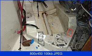
I’ve been following this post pretty closely as adding a 4th engine mount is something I’ve considered doing in the future. My M-25 vibrates a lot at low rpms. I’ve always wondered if those vibrations are working loose what’s left of the old sealant on all my deck fittings.

I thought it a little unfortunate that you’re considering going back to the 3 point mount, after all the progress you’ve made in the other direction. I get what the Isoflex guy said about weight on the mounts, but it sounds like the stiffness of the “rubber” material can be varied, so you may be able to compensate for the light weight.

People have voiced many ideas about ways to address your problem. I’ll just add one more:

It seems that the real strength in these engine stringer design comes from the box-beam type construction. Any one of the 3 (top, front, back) stringer surfaces is only ¼” (if FRP) to 1” thick (if FRP and wood). Join three of these surfaces close together in a box-like fashion, though, and they becomes extremely rigid (particularly at their corners). But, because they are thin surfaces, they don’t hold heavily loaded fasteners (bolts, lag screws) well. A way to exploit the strengths of the design, might be to simply surface-mount a u-shaped bracket around the three FG surfaces. Something like this, onto which you can attach the motor mounts:

Stringer Bracket.jpg

8 to 12 screws holding a 3 sided metal plate against 3 FG surfaces should be extremely strong, and the forces would be spread out evenly over the 3 surfaces and the many screws. You could have threaded studs welded to the top plate to hold the motor mounts, or you could have threaded nuts welded below the top plate to bolt the mounts down into.

A mount like this would let you combine your options 1 & 2 from post #19 if you skewed the attachment of the top plate in relation to the side flanges. This would allow you to align the front mounts with the rear mounts. You could also extend the top plate fore and/or aft of the side flanges to adjust the fore-aft placement of the mounts. Might look like this:

Stringer Brackets.jpgStringer Bracket.2.jpg
i.e., the side flanges lie flat against the angled sides of your engine stringer, but the top plate is in alignment with the rear engine mounts as in the picture below.

Just some thoughts. Good luck!
 

Attachments

  • Engine Mounts.jpg
    Engine Mounts.jpg
    27.4 KB · Views: 205

Ian S

Member III
Good ideas Kenneth! I really enjoy all the creativeness that comes out of these posts! In re; to the M25 vibration I can attest that it drove me nuts for years and going to the four point system made a big difference for me. I also know that iso-flex used to make a softer insert which they discontinued. I bought up the last couple they had. funny to say that when watching the engine run and vibrate I have often thought about going to the stiffer insert as I feel that they may attenuate the vibrations even better? just no way to know without trying them. so I don't think I would be put off by the currently available inserts which I believe are black. They identify stiffness by color code if I remember correctly?

Capt. Ian
 

Rocinante33

Contributing Partner
Yellow Isoflex inserts

Isoflex recommends yellow insert for M-25

Hello Keith,

Thank you for your inquiry.
Attached is the mount we would recommend for your application. The durometer of the mount would be our 50 durometer ( Yellow) Please check the dimensions are like your existing mounts.
Our polymer mounts have may advantages to conventional rubber mounts. Such as impervious to petroleum products, highly resistant to rust (SS hardware and our tee bushings are Zinc plated), fail safe design ( rated to 6Gs in all directions included inverted) . Our Studs are removable to reduce having to lift the engine and gear to install or remove. The cores ( yellow in your case) are two stage so they are stiffer latterly ( to absorb engine thrust while keeping alignment accurate) while being soft enough to dampen engine vibration. I will send you a photo of one of our Cores / inserts to give you a better understanding of this.

There are cheaper mount on the market but you get what you pay for. Our mounts retail for 120.00 each and will discount them 20% to 96.00 each.
Let me know they will fit and this is to your liking.

Best regards,

Jonathan Lucco
Vice President, Americas

Isoflex Technologies International, LLC
561-210-5170 Phone
561-271-9820 Cell
888-327-9260 Toll Free
jon.lucco@isoflextech.com
www.isoflextech.com
http://isoflex.com.au/wp-content/themes/isoflex/images/logo.png
Vibration Isolation Mounts & Couplings
Marine – Industrial – Power Generation – Mining Equipment
 
Top