• Untitled Document

    Join us on April 26th, 7pm EST

    for the CBEC Virtual Meeting

    All EYO members and followers are welcome to join the fun and get to know the guest speaker!

    See the link below for login credentials and join us!

    April Meeting Info

    (dismiss this notice by hitting 'X', upper right)

Compression post base replacement E25

gargrag

Member II
Hi there, I want to check if other people here have had the common issue of the rotten compression post base that's between the keel and the cabin sole, underneath the post.


@trickdhat has an amazing post on how he repaired his boat, with a very creative solution made out of stainless steel. I'm 90% going with the same approach, but I think replacing with solid wood, the original method may be more suitable for me, as the local steel shops want to charge me an arm an a leg for the piece, and the wooden piece I can probably work it myself, seal it and tab it
 

Nick J

Sustaining Member
Moderator
Blogs Author
Thanks for the shout out. Sorry to hear you're having a hard time finding a fabricator. I was lucky enough to find a great shop that was really easy to work with. If I remember correctly, the fabrication was under $200 and the material was around $100. I did purchase the material by myself and brought it to them. I don't know if that would make a difference, but it might be worth a try if you go down that path.

replacing the block is a good option if you can figure out how to get it in place and provide the support needed to lift the sole. You might be able to use wedges or a some kind of a split block that you hammer into place. One of the issues is the contour of the hull in that area. You want the weight to be supported by the keel and not the fiberglass. If you do go down this path, quite a few members recommended using G10 which is a great idea. It's more difficult to work with, but would be a permanent fix.

Regardless of the path you take, make sure you remove the piece of trim between the compression post and the bulkhead in the head before you start lifting the sole. On my boat, it had screws going into both pieces. With it in place, it creates additional friction that makes it more difficult to lift the compression post. The trim hides the wiring going to the mast, so it's also a good opportunity to make sure it is in good working order and well sealed.

While I was researching this project, I ran into quite a few Catalina 30 blogs. A lot of them were pretty bad repairs, but it gives another perspective on a similar repair. I'm sure there's other boats out there with a similar construction for additional data points. Good luck and keep us posted!
 

gargrag

Member II
I asked another friend, that's building a sailboat from scratch in Canada, he thinks I may be able to use laminated G10 or very well laminated plywood.
What I see now is a V shaped block it doesn't touch the sides of the hull. Will keep scratching my head
 

Nick J

Sustaining Member
Moderator
Blogs Author
Your lucky your block still resembled a piece of wood. Mine looked like oatmeal when I removed it.

I think it was a few weeks. It could have been a few days, but I'm pretty slow when it comes to boat work.
 

gargrag

Member II
Your lucky your block still resembled a piece of wood. Mine looked like oatmeal when I removed it.

I think it was a few weeks. It could have been a few days, but I'm pretty slow when it comes to boat work.
do you by any chance still have the measures for the final jackscrew?
 

Nick J

Sustaining Member
Moderator
Blogs Author
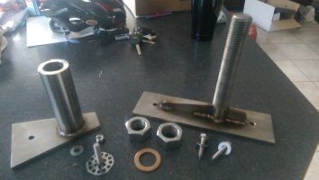
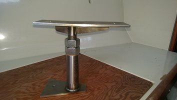
I lost a lot of drawings and pictures of Luffalee when our home laptop crashed a few years ago including the drawing for the jack screw. However, the fabricator I worked with preferred a mock up over drawings. The jack screw consisted of two pieces of 1/4" stainless plate, a 1" section of threaded rod, and a tube with a 1" ID (I don't recall what the OD was, but I think the wall thickness was around 1/4"). I used two nuts, one to provide the force and a lock nut so it didn't back off over time. I also added an oil infused brass washer between the tube and the bottom nut.

I used some cheap poplar ply and a dowel to mock up the part. I started by shaping the bottom piece to fit on the keel. The top piece was just a rectangle. I used a spot of hot glue to hold the top piece to the bottom of the sole and keep the bottom piece in place. I measured between the two plates and cut the dowel down to size then hot glued it to both the top and bottom pieces. Then I carefully removed the whole piece and used screws to fasten it together so it wouldn't move while I took it to the fabricator.

The fabricator cut all the pieces to size, faced both ends of the threaded rod and tube, machined the threads off the top of the threaded rod, and welded it all together. They finished it off by deburring everything.

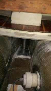
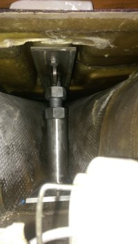
The bottom plate measurement should be failry simple to get by measuring, cutting a template from a piece of paper, then transferring that to the mock up part. The top plate should just require measuring the bottom of the sole where the compression post rests. I made mine removeable by securing with bolts to the bottom of the sole, and a stud epoxied to the top of the keel. If you go this route, make sure you thoroughly wax the bottom of the part before bedding in epoxy and make sure no epoxy goes over the top edge of the bottom plate. It would also help to bevel the sides of the bottom plate, but this would require more work from fabricator and could increase the cost of the part. IMAG1102.jpgIMAG1124.jpgIMAG1181.jpgIMAG1146.jpg
 
Top