• Untitled Document

    Join us on April 26th, 7pm EST

    for the CBEC Virtual Meeting

    All EYO members and followers are welcome to join the fun and get to know the guest speaker!

    See the link below for login credentials and join us!

    April Meeting Info

    (dismiss this notice by hitting 'X', upper right)

Electrical System Question

bigd14

Contributing Partner
Blogs Author
I have an electrical system question. I am starting to plan my system and running into some confusion regarding grounding. I have no experience with boat wiring so I have consulted Casey's, Wing's, and Calder's books and various other sources (and searched here). And I am getting mixed messages-imagine that!

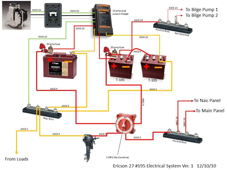
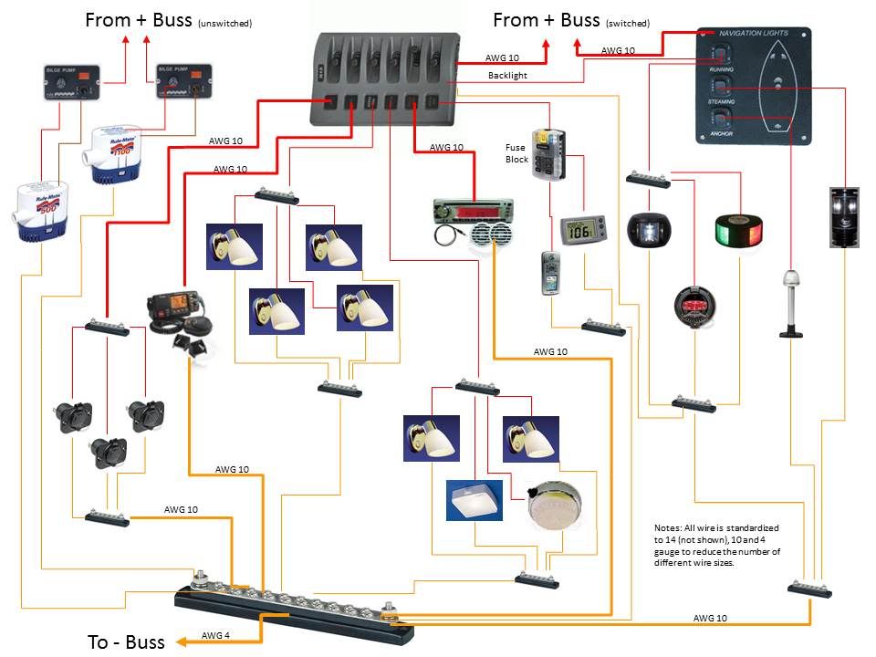
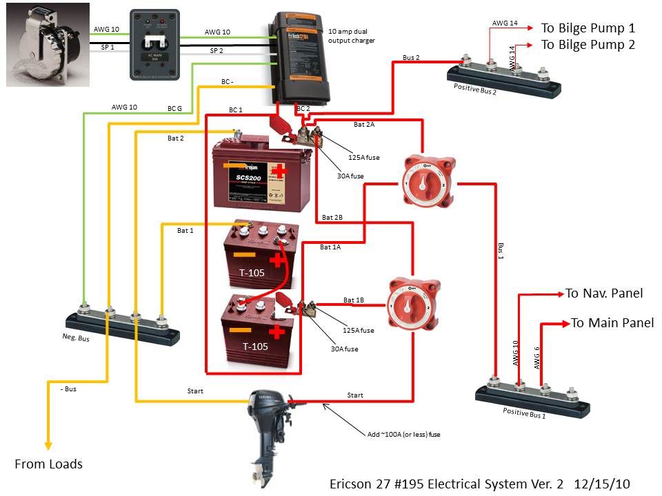
My system will be pretty basic- a house battery running nav lights, house lights, bilge pump, a couple 12v outlets, and instruments, and a dedicated starting battery for the outboard (electric start with a small generator/rectifier). However, here is the rub- since I have no inboard engine I don't have a main boat ground. I cant use the outboard since it will be tilted up when sailing and dockside. On the DC side this is not a big deal I intend to just isolate everything that's in the water. And I am pretty sure I can simply ground above-waterline things like the fuel tank and deck fill to the negative battery post to prevent static build up.

However, its on the AC side where I am having some doubts. The only AC I intend to have is a battery charger charging both batteries. However I understand that simply connecting the battery charger to a dockside GFCI with an extension cord is asking for trouble, and that I should be installing a proper shorepower AC setup (however small) that will at least run the charger. However the three books I have read assume an inboard engine and that I should be connecting the green grounding wire from the AC side to the boat ground in case the charger has an issue and becomes "hot" (and then dealing with the galvanic corrosion issues). But since I don't have a boat ground, what should I do? The only concrete advice I have found in this regard is from EZ AC/DC on their website instruction for their all-in one AC panels where they say I can connect the green AC grounding wire to the negative battery terminal but I have not seen that anywhere else.

If anyone has any advice I would like to hear it (including telling me to go and hire a professional cause I have no clue what i am talking about and I'm liable to kill someone).

Thanks,

Doug
 

Stu Jackson

C34IA Secretary
Doug,

No inboard engine means your battery negative IS the system ground.

AC: three wires in, that's all you need to know. The system is grounded at the shore side of the dock's power system. Better to have a "marine" connector rather than an "extension cord" for safety. Also understand what your dock supply connection is going to be for you. Don't connect the AC ground to the DC ground. There have been decades of arguments about this, but with your outboard and simple DC system, you simply do not need to consider doing this.
 
Last edited:

Maine Sail

Member III
Doug,

No inboard engine means your battery negative IS the system ground.

AC: three wires in, that's all you need to know. The system is grounded at the shore side of the dock's power system. Better to have a "marine" connector rather than an "extension cord" for safety. Also understand what your dock supply connection is going to be for you. Don't connect the AC ground to the DC ground. There have been decades of arguments about this, but with your outboard and simple DC system, you simply do not need to consider doing this.


Stu,

What the OP read is correct as far as industry and insurance company accepted safety standards go.. AC grounding/Earth (green wire) is always suggested to be grounded on-board the vessel to the DC system, not only back at the shore transformer.. This has not been debated in at least the last four revisions of ABYC E-11 and its predecessors going back well over 15 years.

If your boat has a keel bolt that could be sufficient ground in many cases. Alternatively, if you want to wire in a ground buss, basically a big terminal buss bar for - connections. The neg buss bar then runs back to the - battery post on ungrounded DC systems. Other wise just ground everything to the - terminal of the DC battery inclusive of the the green AC wire once on-board.

From the current ABYC E-11 Standards:

11.5.4.7 DC System Negative Connections

11.5.4.7.1 If an alternating current (AC) system is installed, the main AC system grounding bus shall be connected to

11.5.4.7.1.1 the engine negative terminal or the DC main negative bus on grounded DC systems, or

11.5.4.7.1.2 the boat’s DC grounding bus in installations using ungrounded DC electrical systems.

11.5.4.7.2 The negative terminal of the battery, and the negative side of the DC system, shall be connected to the engine negative terminal or its bus. On boats with outboard motors, the load return lines shall be connected to the battery negative terminal or its bus, unless specific provision is made by the outboard motor manufacturer for connection to the engine negative terminal.

11.5.5 GENERAL REQUIREMENTS - AC SYSTEMS

11.5.5.2 Grounded Neutral - A grounded neutral system is required. The neutral for AC power sources
shall be grounded only at the following points:

11.5.5.2.1 The shore power neutral is grounded through the shore power cable and shall not be grounded on board the boat.

11.5.5.3 The main AC system grounding bus shall be connected to

11.5.5.3.1 the engine negative terminal or the DC main negative bus on grounded DC systems, or

11.5.5.3.2 the boat’s DC grounding bus in installations using ungrounded DC electrical systems.


So basically

AC White/Neutral goes back to shore through the shore power cable.

AC Green/Ground does not only go back through the shore power cable, once on the boat, it is grounded on-board the boat to the DC grounding point.
 
Last edited:

bigd14

Contributing Partner
Blogs Author
Thanks for the replies Stu and Maine Sail. Sounds pretty straightforward, I'll connect green grounding wire to negative buss and thence negative battery terminal. And of course get the proper shore power connections.

Doug
 

Tom Metzger

Sustaining Partner
New electrical standards

The new ABYC electrical standards that went into effect in August along with their other standards are now available free on line with a five day trial membership. It can be printed or copied, but it's a little time consuming.

I learned this from Bob Adriance at BoatUS's Seaworthy publication.

http://www.abycinc.org/rulefinder/freedemo.cfm
 

bigd14

Contributing Partner
Blogs Author
I'm still planning the electrical system, and more questions keep coming up that aren't answered by resources at hand...

1. Whether I should use a battery combiner switch and ACR with a small outboard. Since I only have a very small alternator/rectifier giving me (I think) about 6amps at WOT and probably 3 during normal operation, I was originally thinking I would keep the engine starting system entirely seperate from the house batteries, and just let the outboard charge the start battery. Now I am wondering if it might be beneficial to allow it to charge the house battery too, and have the added benefit of being able to combine house and start for emergency starting power. So, is it smart to use an ACR with an outboard given the minimal charging capacity?

2. I am going to have 2 bilge pumps- a 500gph and an 1100gph. Should I wire them to seperate batteries? I am considering wiring the 500 to the house battery and the 1100 to the start battery, thinking that if I get into a situation where I need the 1100gph I had better have the engine running and be heading for a haulout as quickly as possible.

3. If I do not use a combiner switch and ACR, the shorepower battery charger will the only common link between the two battery banks. In this case should I go ahead and connect both negative battery posts to the negative buss to ensure that everything has a common ground (note that the negative battery post is the ships ground since I don't have an inboard to use for that)? I think I would have connect the negatives anyway if I did use the combiner and ACR.

That's all for now! Thanks!

Doug
 

Stu Jackson

C34IA Secretary
Doug, here's a discussion similar to yours, read all the pages of the topic: http://www.sailnet.com/forums/electrical-systems/69467-emergency-battery-charge.html

In your case, using an ACR (combiner) may make little sense. If you're just daysailing and can plug in with your limited house loads, I wouldn't bother with the complexities of the ACR. I'd also run your outboard output to the house bank instead of the start bank, since the engine doesn't need a lot of power to start it. Alternatively, use the ACR, still to the house bank, and the start bank will take what it needs when the engine is running.

There's no benefit in combining the two banks for emergencies, because if one bank isn't working, then the very LAST thing you want to do is combine a bad bank with a good one. This is a very common misconception.

Your #3 is correct.
 
Last edited:

Tom Metzger

Sustaining Partner
There's no benefit in combining the two banks for emergencies, because if one bank isn't working, then the very LAST thing you want to do is combine a bad bank with a good one. This is a very common misconception.
I wouldn't agree with this statement unless you are defining a "bad" battery as having totally failed. If the starting battery is discharged too much to start the engine combining it with the house bank will provide additional power to get the engine started. If you are the belt and suspender type, and also have a length of line tied for extra security, you might want to physically interchange house and start batteries when your start battery is weak, but I don't recommend it as a first approach.

I would also question if a small outboard can separate the charging circuit from the starting circuit. I think on most engines the charging is through the start battery connections.

As for Doug's questions, I would not put in an ACR, but would put in a paralleling switch for the voltage support while powering and the emergency start capability. A 30 amp fuse should suffice. If Doug's estimate is correct about the alternator output with a load on the house bank there may not be enough output to operate the ACR.
 

Maine Sail

Member III
I wouldn't agree with this statement unless you are defining a "bad" battery as having totally failed. If the starting battery is discharged too much to start the engine combining it with the house bank will provide additional power to get the engine started.

Yes that will work if the start battery is dead. If however you have a 1/2/ALL/OFF switch the easiest thing to do is to flip to the charged bank especially if it is the larger house bank that has been killed.

In the OP's situation it does not much matter as it seems both banks are of similar size. More often than not I find owners that start and do everything off the house bank. If they kill a bank of 450Ah's and try to use the ALL function of the 1/2/ALL switch the dead 450 Ah bank can put a large dent in the CA of a small group 24. With AGM's this happens even faster.

If you are the belt and suspender type, and also have a length of line tied for extra security, you might want to physically interchange house and start batteries when your start battery is weak, but I don't recommend it as a first approach.

I would not recommend that as a first approach either. One benefit of small outboard is the ability to pull start them.. Much easier than swapping a battery. I know many outboard cruiser who have just one bank and if it dies they simply pull start the motor.


As for Doug's questions, I would not put in an ACR, but would put in a paralleling switch for the voltage support while powering and the emergency start capability. A 30 amp fuse should suffice. If Doug's estimate is correct about the alternator output with a load on the house bank there may not be enough output to operate the ACR.

I would not put an ACR in this scenario either. Perhaps an Echo Charger, but this is certainly overkill, both an ACR or Echo seems like a bit much for such a simple system with such limited charging capability. Even a small group 24 battery should start that motor 30-40+ times. So you should have no worries when away from the dock for even a week or so.

Our 44 HP diesel consumes less than 0.1 Ah off a 240 Ah bank to start.. Starting my motor 40 times uses about 4 Ah's off the bank. A small outboard would be considerably less starting current than would be required to start a 44 HP diesel..
 
Last edited:

bigd14

Contributing Partner
Blogs Author
Ahh, excellent info, thanks to all.

So I think I will connect the engine to the main battery bank (225ah bank using 2 6v T105 batteries), use a 1, 2, off battery switch, and have a 75 or 100ah back up battery. So what little charge I get from the motor will go back to the house bank and the backup battery will only get charged from shore power (a two output shore power charger). I will not use a combiner switch to avoid draining the emergency bank.

By the way my total load will be about 54ah for overnighters, and about 35ah for long day sails so 225 plus a 75 or 100ah backup should give me plenty of juice for a long weekend with ~50 percent discharge and I can go deeper for the one or two longer trips we might take each year. There is an emergency pull start feature on the outboard if we have to run the batteries way down. I'm working on a diagram which I'll post soon.

Doug
 
Last edited:

bigd14

Contributing Partner
Blogs Author
Electrical Diagrams

Here are the diagrams. Took awhile! One is the battery management side the other the DC side. I am also attaching the spreadsheet that I used to figure loads and wire sizing. Still need to figure out some fusing. But its a start! Any comments and suggestions are welcome.
Doug


View attachment E27 Electrical Draw Version 1.pdf


Battery Side
E27ElectricalSystemPage1.jpg


DC Side
E27ElectricalSystemPage2.jpg
 

exoduse35

Sustaining Member
I would add a circuit breaker in line between the battery and the buss for the bilge pumps. I see where you are going with running them direct but some protection is in order. They make them that are in line with an auto reset so it will do what you want but provide a self resetting fuse in case a pump shorts. Otherwise it looks good. VW used to make their drawings that way...They were also in color so they matched each wire and they oriented the components roughly where the were located in the vehicle. It made following one simple! Keep the diagram when you are done, someday you will want it again! Edd
 

bigd14

Contributing Partner
Blogs Author
thanks Exodus. Thats a good point. I looked around for a auto reset circuit breaker and didn't really find anything that looked suitable. Do you have a specific model in mind?

I posted this question at plasticclassicforum too, but figured I should ask here too. I probably need to up my 30 amp fuse at the battery terminal considerably to handle starter loads for the outboard. I haven't been able to figure out how much current the little outboard starter draws. The rest of the system only draws 23 amps with everything on (not a likely scenario) so I want to keep the fusing somewhat reasonable. Any thoughts how high I should go (max 150 for 4 gauge wire). What are those of you with outboards using?

Thanks,

Doug
 

Loren Beach

O34 - Portland, OR
Senior Moderator
Blogs Author
One bit of electrical trivia I recall is that fuses are sized to wire and not to devices. So the gauge of wire will probably indicate the fuse amperage size.
Loren
 

Tom Metzger

Sustaining Partner
One bit of electrical trivia I recall is that fuses are sized to wire and not to devices.
Loren - This is generally a good idea if the load on the wire is a large percentage of the wire's rating. It doesn't work so well if the load is much smaller then that rating. A relatively small short circuit current in a piece of equipment can start a big fire while not approaching the rating of the wire.

A separate fuse at the load device resolves this situation. This fuse must be at least one size smaller than the branch circuit fuse or breaker so it will always blow first.
 

bigd14

Contributing Partner
Blogs Author
I may have to rethink my setup, since the way it is now I have a single 30 amp fuse protecting 4, 10 and 14 gauge wires. I think i will have to run everything to a fuse block and protect each one with a different size fuse. And putting a slightly smaller fuse near the engine sounds like it might be a good idea.

Back to the drawing board!

thanks

Doug
 

bigd14

Contributing Partner
Blogs Author
Here is a new diagram. Wondering if a double battery switch with multiple fuses at the battery terminal would work... Seems a little complicated!

E27ElectricalSystemPage1TwoBattSwitch.jpg
 

exoduse35

Sustaining Member
Doug, I think the easiest place to find one would be a large RV supplier. It is a bit more difficult but they can be ordered from a good auto parts store. I don't Know of any straight up marine item. As for brand I think they are made by Cole Hersey. You should get a spare and then take measures to seal it. Edd
 

Maine Sail

Member III
The fuses at or within 7" of the battery are intended to protect the battery wiring and should not be rated at more than 150% of the ampacity rating from ABYC E-11 Table VI. (I think in the last version of E-11 this was called table IV)

Each "branch circuit" from the main panel should also have its own fuse protection as well as any small device fuses that are necessary.

I don't understand the desire for two 1/2/BOTH/OFF switches in the last diagram. I'd keep it simple with a single 1/2/BOTH/OFF and you'll be more than fine. All you need to do at the battery is fuse any wire coming directly off if it on the hot leg at the ampacity rating of the wire or up to 150% of that rating. I generally size my wire so that I can fuse at 100% or less. So a bilge pump, charger, inverter or battery cable would get fused at the battery to protect the wire. If the device needs it's ow fuse one can be added at it. There is also no problem in de-rating a fuse at the battery to protect the device if you want to as this would also protect the wire. Marine wiring is usually done on a supply, load, branch, device type of install. The batteries, in your case, being supply, the breaker panels being load distribution, with a main breaker, and the wires running from the individual branch circuit breakers go off to the devices where there are often more fuses.

For example E-11 suggests that 16 AWG should be the smallest wire used on-board, unless very specific criteria are met for an exemption, but this 16GA wire is often powering a load like a hand held GPS with just a .2A draw or a wind instrument etc. with equally low load. So the 16 GA wire gets protected by a circuit breaker at the panel but they don't make circuit breakers in a .5A rating so you then need a .5A fuse at the GPS/device as well.

The finished install looks like this; Battery fuse, panel main breaker, panel branch circuit breakers, device fuses.

When you use a "circuit breaker" it should have an AIC rating of at least the CA of the battery bank or you could risk welding the contacts, and not protect anything. AIC is amperage interrupt current. Some breakers have less than 1000A AIC ratings and two T-105's can supply more than 1000 CA. Blue Seas makes some 3000 AIC rated circuit breakers but they cost more. This is less of an issue with small banks but with TPPL, AGM and big banks finding a breaker that has an AIC rating meeting that of the bank is a next to impossible task. For your system you are well covered in the AIC department using ANL or MRBF fuses and even some of the better circuit breakers but do check the AIC ratings..

You can call the engine maker and find out the cold rated starter current. You really don't need to worry about the in-rush load as this is usually well under 2/10 of a second and the fuse will not blow if otherwise sized correctly. If the starter cable for the OB is sized appropriately for the load you can just size the fuse to that or 150%.

BTW the ampacity rating for 4 AWG 105C temp rated wire is 160 amps outside of engine spaces and 136 amps inside engine spaces. There is little possibility that your small OB draws anywhere near 160 amps of starting current. You should be able to easily size your fuse for under 100% of the ampacity rating.
 
Last edited:
Top