• Untitled Document

    Join us on April 26th, 7pm EST

    for the CBEC Virtual Meeting

    All EYO members and followers are welcome to join the fun and get to know the guest speaker!

    See the link below for login credentials and join us!

    April Meeting Info

    (dismiss this notice by hitting 'X', upper right)

Replacing the Steering Pedestal

Michael Edwards

Member II
This is AnnaDor’s wheel. It’s not not an Edson but just like one.
 

Attachments

  • AA5D4E22-9C0D-4D4A-BC26-1740890EFF54.jpeg
    AA5D4E22-9C0D-4D4A-BC26-1740890EFF54.jpeg
    302.6 KB · Views: 21

Michael Edwards

Member II
I wonder if you are thinking of mounting the pedistal ahead of the rudder post. I mention this because on our boat all of the moving parts are aft and are reachable from the aft locker. Literally below the bridge deck.
 

Loren Beach

O34 - Portland, OR
Senior Moderator
Blogs Author
I wonder if you are thinking of mounting the pedistal ahead of the rudder post. I mention this because on our boat all of the moving parts are aft and are reachable from the aft locker. Literally below the bridge deck.
For comparison sake, remember that the cockpits are different for the 32-2 model and the later 32-3 model.
 

GrandpaSteve

Sustaining Member
Hello everyone. My pedestal is fine. I am just curious after watching an Edson Vision install video on YouTube. I wanted to see if anyone here had gone through the trouble/expense of installing one. I saw it while looking for ideas about electronics cable routing.
 

Loren Beach

O34 - Portland, OR
Senior Moderator
Blogs Author
Regarding cable routing- The only cable inside the original column was the twisted wires for the compass light. While other cabling could theoretically be added, like the AP power, or the instruments and then plotter and radar feeds, these usually end up in one or both sides of the SS guard tubing. Anything in that central column has a risk of chafing on the steering apparatus.

A friend of mine with an E-38 changed out the guard for a new 1 1/4" version, and this made the cable runes a LOT easier.
I have the AP cable on one leg and -with some difficulty - the plotter/radar 3 cables in the other leg. This is in the original 1" tubing. If starting over, I would also change to the larger tube sizing. Note that such a change does require a new plate under the compass housing with larger passage holes for the tubing. Anodysed aluminum is good for this or G10. The 'feet' of the tubing will then be welded on.

Note B: if/when you ever remove the steering column for re-bedding, check the inside of the base casting carefully for corrosion.
We had this all repainted last year when the boat was apart, and it was in perfect shape. Not everyone is so lucky.
 

GrandpaSteve

Sustaining Member
Regarding cable routing- The only cable inside the original column was the twisted wires for the compass light. While other cabling could theoretically be added, like the AP power, or the instruments and then plotter and radar feeds, these usually end up in one or both sides of the SS guard tubing. Anything in that central column has a risk of chafing on the steering apparatus.

A friend of mine with an E-38 changed out the guard for a new 1 1/4" version, and this made the cable runes a LOT easier.
I have the AP cable on one leg and -with some difficulty - the plotter/radar 3 cables in the other leg. This is in the original 1" tubing. If starting over, I would also change to the larger tube sizing. Note that such a change does require a new plate under the compass housing with larger passage holes for the tubing. Anodysed aluminum is good for this or G10. The 'feet' of the tubing will then be welded on.

Note B: if/when you ever remove the steering column for re-bedding, check the inside of the base casting carefully for corrosion.
We had this all repainted last year when the boat was apart, and it was in perfect shape. Not everyone is so lucky.
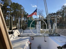
Right. What I have now in the pedestal guard tubes is crowded. The old Data Marine depth sounder power and transducer wire, that still works, the AP motor wire, the AP control head wire (NEMA 2000, which is cool because I can connect the chart plotter and AP together at the pedestal with a short NEMA 2000 cable), the chart plotter power wire. and something else. What I have no room to add in the tubes is the new transducer wire. I ran it through the cockpit last season, and I sailed alone most of the season so I didn't have to tell many people to watch out for it. I could loose the old Data Marine unit, but it still works.
 

Christian Williams

E381 - Los Angeles
Senior Moderator
Blogs Author
There are two pedestal guard tubes to use for wiring.

Although not recommended, I cut the transducer wire for the chartplotter because the plug wouldn't fit through my half-inch access hole in the tube.

Such a wire is possible to rejoin, or at least my simple splice has worked for two boats.

transducer splice.jpg
 

GrandpaSteve

Sustaining Member
Thanks everyone. I hope these answers are helpful for the archive. I really was curious to see if anyone in the forum had installed the Edson Vision pedestal, based on these answers I assume not.
 
Top