E32-3 Going Overboard with the Engine Instrument Panel

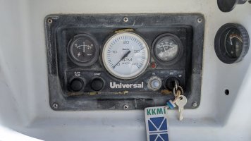
Before...
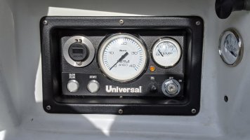
...After
IMG_20200808_150646 (1).jpg
PXL_20210404_182201316 (1).jpg

It's amazing what a little fresh paint and new gauges will do for an engine instrument panel.

And, a box of new marine grade wire, some fancy LED-backlit buttons, a grip of heat-shrink ring terminals, a heat gun burn on my upper arm, 1/8" weatherproof rubber matting, some oversized washers, a little sweat, and a bit of a lower spinal pain from sitting in the starboard lazerette.

When I got done my slip neighbor, @Fnagelmann, took a look and said, "There you go.. making my boat look bad again!"

Wiring Design​

I usually start with a drawing or diagram when working on projects like this. I think in spatial terms -- seeing what I'm going to build or change helps me conceptualize all the parts and steps needed. Here are the color keys for the wiring below, which I attempted to get as close to ABYC standards as possible:
  • Blue = illumination power
  • Purple = pumps, instrument power
  • Yellow = starter circuits
  • Red = positive mains
  • Orange = accessories
You can probably find a couple slight exceptions, as I didn't want to buy an entire spool of wire for a single run in some places ;-)

rumour_m25_engine_instruments-Cockpit Instr Panel.png


Regardless of the amount of prep, drawing, thinking, etc I consistently ran out of connectors, tools, wire, and patience. Like most boat projects of substance this stretched the timeline over a couple weeks, a few Spotify playlists, and multiple beers in the early evening sunshine.

I kept the focus on the cockpit engine panel side of the connections. In a future upgrade I'll be completely replacing the 'trailer harness' cabling between the engine bay and the panel (see diagram at the bottom of this article). Even with the restriction of just the control panel, there was a lot to consider. As most of us know, our boats were often wired with haphazard manners and without regard for ease of troubleshooting. That's actually a great segue into the tear down process...

Tear Down​

PXL_20210322_021421399.jpg
PXL_20210322_022450487.jpg
The rats nest of wires, corroded contacts, fuses in interesting places, and non-marine connectors came apart relatively easily. I spent just enough time tracing all the wires to make sure I understood how it was originally wired.


The ammeter gauge was broken (not a big surprise). The other gauges were functioning, but I ripped them out in favor of new Faria Beede models. The more I dug and unbolted, the more I realized hardly anything should be reused.

The fuel and engine hours gauges were mounted off the panel against the cockpit combing under the lid of the starboard lazarette. Fuel functioned while the engine hours gauge did not. I soon discovered it was merely because of a corroded disconnect -- a soft reminder to always check the basics before moving to replace something not working.

Cosmetics​

Once I got the panel back to the garage workbench, I stripped it all the way down. I didn't want to just have a rewired panel which functioned well. I wanted it to look good too. There were a few stress cracks in the plastic which I shored up with J-B Weld. Using a Dremel, I reshaped a few of the mounting holes for new instruments and switches. I ordered a sheet of rubber matting from McMaster Carr to place over the front of the panel, but behind the Universal placard. My thought was it might help prevent water intrusion -- but this is a bit of silly thought since I didn't seal the gauges just above. At the very least it made the Universal placard stand out a bit more.

I painted the entire panel, front and back, with Rustoleum 2X Paint/Primer in flat black. Did the same to the Universal placard after masking off the labels.

PXL_20210324_001903997.jpg
PXL_20210325_220830192.jpg
PXL_20210325_220838605.jpg

Upgrades & Fixes​

Intermittent Starting Issues​

Like a lot of mid 1980s Ericsons, Rumour had intermittent engine starting issues when I first took ownership. Sometimes when the starter button was pressed there would be a click from the engine bay with no engine cranking just following. I was originally resistant to the advice on this forum to make a couple light modifications to the engine wiring. Instead I tried to troubleshoot other ways. You can see both my resistance and repentance in this thread.

The real kicker here was swapping out the wire running from the start switch to the solenoid post of the starter with a large gauge wire. Since the ammeter was being removed, this freed up a 10ga orange wire for the cause. Once this was done the engine turns over every time without fail.

New Gauges​

I bought and installed all new gauges from Faria Beede which all match one another. Fortunately, all the sensors seemed to be working appropriately, so it was just a drop-in replacement.

Separate Accessory & Ignition Busses​

This idea came from a couple other threads. I bought a Blue Seas Split Bus Fuse Block. This helped allow for a couple improvements:
  1. Unique fuses for the various circuits involved with the engine and instrument panel
  2. Separating the accessory bus from the ignition bus. This means I could power the blower or the USB charger without needing to energize the ignition circuit
  3. A common ground bus for all circuits

Voltmeter & USB Charging​

After removing the ammeter I wanted to have a voltmeter to see the condition of the selected battery. I know this isn't perfect, but it's just a nice to have. Amazon has a bunch of these devices which include USB charging. I chose one with USB-A and USB-C connectors, the latter of which has enough juice to rapidly charge my phone and even charge my laptop.

No More Incandescent Illumination​

I pulled all the bulbs from the gauges and replaced them with red red LEDs from Amazon. I was hopeful this would help maintain the night vision. I replaced the oil pressure alarm light with an LED as well in amber.

Screen Shot 2021-12-25 at 7.26.38 PM.png
Backlit Glow & Start Buttons​

Normally, I would scoff at spending $50 per switch for something like this. But, I couldn't resist. And, I'm glad I didn't. The buttons are made by Blue Seas and are 15A momentary switches which are backlit in two colors. When the switches are energized, they glow blue. When the buttons are pushed they turn red.

On first blush, this may seem like frivolous fanciness. But, I've convinced myself that this could eventually be a fair troubleshooting tool. If the buttons fail to light up, that means there could be an illumination circuit issue, which could also be confirmed by looking at the gauges. If the button is pushed and does not turn red, that means the input voltage for the actual switched circuit is not energized.

Oil Pressure Alarm & Mute/Blower Switch​

I replaced the blower switch with a Blue Seas DPDT (double pole, double throw) toggle switch. This allows me to use the switch as both a "mute" for the oil pressure buzzer and an on/off switch for the blower (Why am I keeping the blower? I guess just peace of mind knowing I can evacuate the air from the engine bay if something were to happen). The positions for the switch are:
  • Up = oil pressure buzzer on
  • Middle = oil pressure buzzer muted
  • Down = blower on
The oil pressure LED will always illuminate regardless of the mute switch.

Finished Product​

PXL_20210404_180839524.MP.jpg
PXL_20210403_035141044.jpg


What's Next?​

The next phase of this project is to replace the trailer park harness and all the wiring running from the panel to the engine block. The wiring itself should be pretty straight forward, but running and securing the cables might take a little time. I might try to couple this with when I install my autopilot, as I'll need to temporarily move the water heater to drill, rebed, and seal the cockpit sole penetrations.


rumour_m25_engine_instruments-Engine Block.drawio.png


Inspirational References​

Blog entry information

Author
vanilladuck
Views
1,046
Comments
14
Last update

More entries in Electrical - 120v and 12v

More entries from vanilladuck

Top