Retired from newspapers and television, currently sailing Thelonious II, a 1984 Ericson 381.
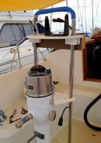
The first wire-snaking job was the transducer cable. A pleasant two hours, sort of, screwing cable clamps at arm’s length. Perhaps you have someone to help you? I did a swell job running the cable and then attempted to join a 6-pin connector to an 8-pin connector. Huh? You gotta be kidding me, but unfortunately nobody was. Recall that, earlier, West Marine countermanded its recommendation for the transducer, saying they had almost given me the wrong one? Well, they had countermanded themselves incorrectly and given me the wrong right one. “Sorry!” So I ripped out all my work and started over. Moral: don’t make anything permanent until the whole system works. [The correct unit was: Airmar P72 trolling motor mount transducer/500w w/temperature/8-pin connector].
But soon the Garmin 50s chartplotter was up and running. It has a large display that’s clear even in direct sunlight. The interface is intuitive. The fathometer/fish-finder screens show no visible interference with engine on, even shooting sonar through the hull. My amateur splice, with wire pairs wrapped in kitchen aluminum foil, appears to work flawlessly. Here’s the rail guard with its three holes. A piece of half-inch plastic tubing slipped around the wire before snaking provides anti-chafe at the tubing exit.
All the wires now tucked through the rail guard are subject to warnings about electrical or magnetic interference. The Garmin head is supposed to be three feet from the magnetic compass. Mine is one foot. The transducer cable is supposed to avoid the battery cables. My Ericson factory wire run goes right through the battery compartment on its way to the panel.
That’s a lot of wires and compromise. The supplied Raymarine SeatalkNG (“New Generation”) cable with its proprietary connectors was barely long enough – if it doesn’treach the panel, ordering a longer cable is recommended. Seatalk NG allows many combinations of instruments using NMEA 2000, and incorporates NMEA 0183. It is so advanced, I would soon learn, that Raymarine didn’t understand it.
The SPX-5 Wheel Pilot package is composed of the P70 control head, a fluxgate compass, a course computer and the mechanical wheel steering components with drive motor. No Rudder Position Indicator is required.
I installed the fluxgate first. It needs to be mid-ships and far from the engine block. I put it in the head, which met the requirements.
The course computer is to be mounted vertically, either athwartships or fore and aft, and the nearer the panel the better. I put it at the nav station desk. Five inputs enter the computer – fluxgate, NMEA forGPS, Seatalk NG for the P70, 12v in and 12v out (for the wheel motor). For most of our boats that probably puts the course computer on a bulkhead with difficult backside access. Leave lots of slack in the wires because the computer needs to be pulled away from the bulkhead to work on.
Two words sum up the evaluation from here on: Raymarine flunked. The SPX-5 box is loaded with half a dozen proprietary Seatalk wires with no identification system whatsoever. You’re supposed to guess what's what..
Two installation guides are included – one for the SPX and one for the P70. They contradict each other at every turn. I powered up the course computer and hooked up the P70 as directed. The multi-meter showed 12v to the computer, but the control head was dead. I spent hours tracing all the wires I had carefully installed and groping through the depths of the panel looking for my error.
I called Raymarine technical help. You can’t get through. I left a specific message three days running. Thirty-six hours later in each case a tech returned my call, not having heard my message. Meantime,the Ray Internet message board glowed with panic: A retired electrical engineer complained that he was unable to install his SPX-5 after a career installing, I don’t know, the space shuttle or something– and every other new owner of the wheel pilot seemed to be in his own personal state of confusion, dudgeon, fury and/or suicidal despair.
Finally, on June 17, a correct wiring diagram was uploaded to the Raymarine “Diagrams”board. Ray didn’t tell you it was there- -you had to ask.
It turns out that every package of this product was shipped with wrong installation instructions. Raymarine knew that, of course. They just sold it – and ducked behind their techs. Nowhere on their message boards did a hint appear that, unlike the former control head, the newer P70 cannot take its 12v from the course computer, it must have its own supply; and its proprietary SeatalkNG connectors must be arranged in a certain specific way. The box contains many of these nameless mystery gizmos, several of which are irrelevant to most configurations. Will Raymarine eventually straighten this out? What’s the hurry, with no real competition.
The easy part was bolting the mechanical steering rim to the ship’s wheel, drilling the pedestal to accept a simple pin, and fixing the power wires to the motor that drives it. Oh, yes – and all of the special Seatalk fittings go together unsatisfyingly and with difficulty, as if the tolerances were slightly off. The connector providing power to the motor, which is subject to rain and spray, doesn’t fit together very positively, either.
Well, ready for a sea trials.
Here is Part III.