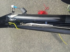
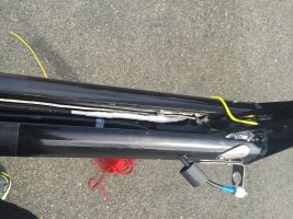
Next phase of the project was to replace lights and wiring. Most of that wasn’t very dramatic, thanks to the design of the Kenyon spar that Ericson used in this era. It is a beautiful design – there’s an aluminum sail-track that slots into the extrusion, and when you pull that track out from the bottom of the mast it exposes a built-in wire channel, the full length of the mast. No fishing wires through conduit or draping them down the middle of the spar for halyard to rub against. This is like magic!
The old coax was on its last legs. Inside the spar was fine, but at the masthead it had been routed out a hole in the top of the mast, around and through an opening in the backstay crane to the bottom of a side-mounted antenna on the opposite side of the mast from where it came out. The coax had rubbed (for years, if not decades) on various edges until the copper braid was exposed (and, in some places, missing). Not sure how that coax was still letting a signal through, but it was!
After asking a lot of questions and reading some great Maine-Sail posts, I “mostly” decided to use LMR-400 UltraFlex for the new coax. Great specs, low loss, good UV-protection, and actually less expensive than the RG-213 at WM. But after the “mostly” I had two concerns – one, about the weight of the 0.400” diameter coax and how I was going to accomplish strain relief inside the wire-channel at the top of a 47-foot rise, and two, bend characteristics. LMR-400UF has a minimum bend radius of 1”, which would have made it “interesting” to route both at the masthead and inside the boat.
Happily, LMR-240 UltraFlex addresses both of those. It is approximately half the weight, has better tolerance for being bent, and has nearly as good a spec as the LMR-400, so I went with it. I shopped around online and ordered a 75-foot pre-made cable from this place, plus a few of the crimp-connectors that Maine-Sail recommends.
http://www.universal-radio.com/catalog/cable/cable.html
I got a pre-made cable because, frankly, I wanted the connector at the top of the mast to have been made by a professional – I may never see it again, and wanted it to be a “good” connection, not a hack-job by some new boat-owner who doesn't understand how electrons are supposed to go thru cable. I estimated the run from masthead to VHF to be about 64 feet, so with a 75-foot cable I had some “extra” to work with, allowing me to get the VHF-end connector right (and maybe even make a couple of patch cables out of the extra). Ran the cable into the hole in the sidewall of the mast, fished it into the wire channel, put on two layers of heat-shrink tubing to protect it from metal edges, installed a cable-clamp at the top to serve as strain-relief and ran it down the length of the mast. Easy-peasy.
The old wiring was probably fine. But I figured as long as I’m doing this I might as well replace it too. Ran 14/2 to the masthead for a new LED anchor light, and 14/3 to the lower spreaders for the combo (steaming/foredeck) light. Ericson and Kenyon very conveniently provided a metal tube from the inside of the wire-channel to the front surface of the spar for the combo light, so running the wire was easy.
The old Perko masthead light was mounted in such a way that the wire came out of a hole in the top of the mast and then bent sideways into the bottom of the light fixture. I don’t like open holes in the top of a mast. And I don’t particularly love exposed wires up there, either. So I found a “Hella” LED fixture which would allow me to run the wires straight up through the hole into the bottom of the light fixture, and the base of the fixture effectively covers the hole. Made the connections, drilled and tapped a couple of small holes for the fasteners and, when done, it is a fairly clean installation.
The only bad thing about doing it this way – and it is really bad, so I gave it a lot of thought - is that the wiring connections and strain-relief are inside the wire-channel behind the sail track, so if the light (or coax) ever fails I’ll have to pull the rig to replace it. The old Perko incandescent light appears to have survived 30 years with its wiring exposed to the elements, if this one – protected somewhat better – goes as long I’ll be very happy.
While there I made a small cover-plate out of kydex and fastened it down over the hole in the masthead that the coax used to come out of. I routed the coax to the bottom of the antenna by a more direct route, so I didn’t need that hole for anything, and I probably could have just left it there but… have I mentioned I don’t like holes in a masthead? Nobody will ever see it, but it makes me feel good. And after all, it’s all about “me”, right?
At the combo light, I really wanted to use an AquaSignal or MarineBeam LED fixture. Both are well-sealed units with replaceable LED bulbs, but I couldn’t find a way to make them work where the wires exited without drilling a bunch of holes. The wire-exit is just above the level of the lower spreader, and it interfered with the mounting options for each light. So I chased down the newer version of the Perko light that had already been on there, installed LED bulbs from MarineBeam and mounted it up using the existing holes. I don’t love the Perko fixture – it feels “cheap” to me and I was never able to convince myself that it was adequately sealed (in fact, the bulb for the foredeck light is barely protected from the elements at all). I guess we’ll see how it does.
I also replaced the antenna. Having done some reading, and having great respect for recommendations Christian made, I planned to install a Vesper AIS at the nav station, so it made sense to install a Vesper dual-use (VHF plus AIS) antenna at the masthead. Only problem was that the Vesper-provided antenna mount would have required me to drill five new holes in the side-wall of the mast, and the Vesper insulating insert wouldn’t fit in the existing mount. A friend of mine is a machinist who loves twisty problems, so I gave it to him. Next day he called me up and handed me the old mount, beautifully milled out so that the Vesper insert would fit. Wouldn’t take my money, but graciously accepted a bottle of Maker’s for his efforts. Seems like a fair trade.
Last major thing to do at the masthead was replace the sheaves and pins. I had originally planned to just reinstall the existing ones, but a couple of things made me decide to replace: for one, the existing main- and jib-halyard sheaves were grooved for wire, and my halyards are all-rope; two the existing sheaves were pretty sloppy on the pins – in some cases because the pins were undersized (nominally 0.375”, but two of them measured around 0.340” in diameter) and in some cases because the holes in the sheaves were oversize (should be slightly more than 0.375”, but in some cases were well over 0.425”). Net effect was that the pins were wobbly in their channels, and the sheaves were wobbly on their pins.
A call to zephyrworks (
www.zephyrworks.com) solved all that. I emailed him the dimensions he asked for, and about a week later I had a full new set of black delrin sheaves, sized for my all-rope halyards and provided with just-the-right-size pins. They’re beautiful, and they fit perfectly. I applied a small amount of lithium grease to the bearing surfaces, put the sheaves into the appropriate places, dropped the pins through them, and then reinstalled the existing plates over the open ends. Slick. I also tapped and threaded the holes I had used to drive the old pins out (I don’t really like holes in a masthead). Some number of years from now my heirs may wonder what those little round-head fasteners at the masthead are for…. Well, they’re there to fill the holes.
You read it here first.
On to
Part 3.