• Untitled Document

    The 2024-2025 Fund Raising Season has Opened!

    EricsonYachts.org has opened the season for raising funds to support the expenses of the site. If you would like to participate, please see the link below for additional information.

    Thanks so much for your continued support of EricsonYachts.org!

    2024-2025 Fund Raising Info

NMEA 2000 power question

bsangs

E35-3 - New Jersey
Anyone here have their NMEA 2000 network backbone attached to a switch? Am adding a Garmin Steadycast to the backbone this week to a get a more accurate heading reading from my chart plotter, before installing my radar, and was thinking of reconfiguring some things while doing so. From what I've read, the NMEA backbone can be a constant power draw, even with no devices active. It's a small draw, maybe .05 amps, but over time, and especially if not connected to a battery charger, that could obviously add up. My backbone is currently not connected to a switch so I'm considering installing one, but not if it's more of mole hill than a mountain.
 

peaman

Sustaining Member
You can certainly power the backbone through a dedicated switch. In my system, I figured I would never use my chart plotter or autopilot without also having wind and depth instruments powered, so my "instruments" circuit breaker powers the backbone, which provides power to a couple of display devices (B&G Triton2) as well as wind, depth, and speed through water.
 

bsangs

E35-3 - New Jersey
Thanks. Think that’s what I’m leaning toward doing. Boat came wired with chart plotter not connected to the breaker box. So that gets powered on and off from the device. Instruments have a dedicated switch on the box, but that only engages the wind meter. Autopilot has a dedicated switch too. I’m giving the radar its own switch, but think the backbone, chart plotter and instruments need to be wired to one breaker.
 

Marlin Prowell

E34 - Bellingham, WA
If you have anything attached to the NMEA 2000 backbone that does not also have a separate power connection, like a depth sounder, then the device is definitely drawing power from the backbone. It may not be much, but is enough to drain the battery over time. I have the NMEA backbone power, chart plotter, and instruments all connected to the Instruments circuit breaker on the electrical panel.
 

Nick J

Contributing Partner
Moderator
Blogs Author
I have my backbone connected to a dedicated instrument breaker as well. I've been digging into my instruments and the NMEA 2000 backbone lately to install a Vesper Cortex. The Cortex has monitoring capability including passing depth, water temp, battery voltage, and wind data from a NMEA network to the remote monitoring app. The problem is I have to keep my instruments powered on while I'm away from the boat if I want to view the data. I would like to have two NMEA power sources; one for displays and other sailing devices and one for sensors. You can do it with connectors that don't pass the source voltage, but that would require all sensors on one side of the bus and displays etc. on the other. For now, I've just decided to keep the NMEA instrument breaker on and put the displays in standby while I'm away.

NMEA 2000 and CAN Bus is a really cool idea for simplicity, but it's not very flexible. The same connectors that make it easy to use make the network difficult to segment. It can also make cable management difficult
 

Marlin Prowell

E34 - Bellingham, WA
The problem is I have to keep my instruments powered on while I'm away from the boat if I want to view the data.
Without knowing your equipment list in detail, I cannot answer this with certainty, but I don’t see why you cannot keep your NMEA bus powered all the time using a separate fused circuit. This will also keep all the transducers that take power from the bus also permanently powered on, which seems like what you want. Everything not powered by the NMEA bus but from the instruments circuit breaker can be turned off when you leave.

Devices that require a separate power source that you wish to leave on, like the Cortex, will need a second instruments circuit breaker or fuse, but none of this requires segmenting the NMEA bus itself.
 

Nick J

Contributing Partner
Moderator
Blogs Author
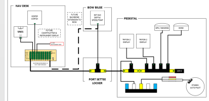
This is what I have today:

1709131179777.png

My problem is self imposed in that I would like to see wind, depth, and a few temperatures (cabin, fridge, and exterior air from the Simarine SN01) while away from the boat. I would like to do this without powering the displays and GPS heading sensor. For present configuration, I could replace the first T with a 2 way, install a power isolator between the 2 and 4 way connectors, move the wind to the open port of the 2 way, and supply a 2nd power supply to the 4 way fed from a new "instrument display" breaker. As soon as I add a display to my Nav desk, it gets more complicated. Again, totally doable, but it's a solution to a self imposed problem. I'll just continue putting the displays in standby. I'm connected to shore power 100% of the time I'm away, so it's not a big deal to me. Just wanted to share my configuration and some of the tradeoffs with the NMEA 2000 wiring.

To directly answer the question in the post, I do like having the option of turning the instrument power off instead of directly powering it from a fuse on the 24hour circuit. This gives me the option to easily turn it off.

For cable management, I'm using a CAN Bus junction circuit board at my nave desk. I tried field installed connectors, but I couldn't find one I trust. Everyone I tried has a screw that directly secures the stranded wire and they aren't big enough to fit ferules. The circuit board allows me to cut of the ends of the cable eliminating large coils at the nav desk. It also provides a lot more ports in a smaller footprint. NMEA 2000 Ts, 2way and 4 way connectors add up quickly and take up a lot of space. This one also has a switchable 120 ohm resistor on the board. It's in a dry location on my boat, so I'm not concerned about the weather protection a NMEA 2000 M12 connector provides.
 
Last edited:

Marlin Prowell

E34 - Bellingham, WA
I realize that I did not make a distinction that is important to this discussion. The NMEA bus has power and ground wires that can supply a small amount of current to devices. I’m suggesting that the NMEA bus power connection be a separate circuit from your instruments circuit breaker. Put a fuse on the NMEA power, connect it to an always on circuit, and hide it behind the DC panel.

Showing which devices require external power and are connected to the instruments circuit breaker in your diagram would be helpful additional information.

Some of these devices I know or can look up their power requirements. The DST810 and SN01 are powered solely from the NMEA 2000 bus, so they would be on whenever the NMEA bus is powered. The PICO device interfaces connected to the SN01 (not shown) would also need to be on the NMEA bus power circuit. The Triton2 displays require external power so they would be turned off when the instruments circuit breaker is turned off. The Vesper Cortex would need to be powered on permanently. As I’m typing this, I see that you probably want a separate circuit breaker for all the “always on” devices, and that includes the NMEA bus power and the Vesper Cortex.

So there is no need to segment the NMEA bus — it can be powered on permanently. You probably just need two instrument circuits.

A different topic. There is a problem with your set up. The Raymarine ST4000+ auto pilot is a Seatalk and NMEA 0183 device. You cannot connect it directly to a NMEA 2000 bus. The data for each network type is entirely different and incompatible. You’ll need a gateway device to translate between NMEA 0183 data and NMEA 2000 data. A lot of chart plotters have both NMEA2000 and NMEA 0183 interfaces and act as gateways, but I don’t see something like that in your diagram.

Connecting NMEA 0183 to a NMEA 2000 bus is a big topic, so we should move this part to a new thread if you want to continue this discussion.
 

Nick J

Contributing Partner
Moderator
Blogs Author
Wow, thanks again for the detailed look into my system. I'm creating some confusion by not making the print detailed enough. I detailed the NMEA 2000 to Seatalk 1 connection for the auto pilot on the post you referenced above. Sticking to the power discussion here.

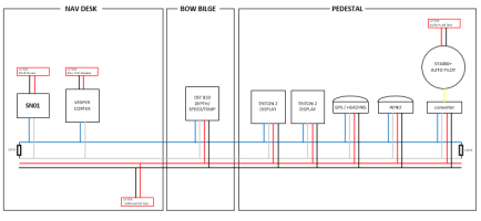
NMEA 2000 wiring consists of 2 pairs of wires; CAN +, CAN -, 12vdc +, 12 vdc -, and a shield. CAN+ and CAN- are used to transport data and the 12vdc provides a minimal amount of power. Not enough to power chart plotters or auto pilots, but it does power the transponders. Displays may fall in the gray area. My B&G Triton2s DO use the NMEA 2000 power supply which is where my original comment is coming from. I also have the GPS / heading sensor that isn't needed while I'm away.

Here's what I currently have in more of a schematic view:
1709164840704.png
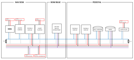
And what I would like:
1709164883412.png
The problem with NMEA 2000 cabling is you can't just easily add a second power wire. You have to decide where you're going to break the 12vdc bus. Everything on one side gets fed from one source and the other side from the other source.
 

Marlin Prowell

E34 - Bellingham, WA
I cannot read the small print for the box supplying power to the SN01, but, in my cursory look at the documentation, it seems the SN01 gets its only power from the NMEA 2000 bus, and not from an external source.
The problem with NMEA 2000 cabling is you can't just easily add a second power wire.
There is a hack that you can try if you can physically split your NMEA 2000 network into the two halves you want. Use this micro powertap tee from Maretron as your power connection. There are two sets of power/ground wires in the cable — one for the left connector and one for the right connector. So you could power one side of the NMEA bus separately from the other. This is definitely not what this power cable is designed for, and no guarantees that the NMEA bus would work properly when only one half is powered. Like I said, a hack. Personally, I wouldn’t do it because it is not playing by the rules, but I don’t know your risk tolerance.

Then there are solutions like this bus extender, which is the correct and expensive way to split a network in two.

You should definitely have the GPS sensor powered on when you are not there! Then you can see when your boat is heading down the fairway when you are not aboard. :oops: Many years ago I had my San Juan 24 stolen, so I might be biased.
 

bsangs

E35-3 - New Jersey
Wow, you guys have MUCH more detailed NMEA networks than I do. Think I have only four devices in mine.
 

peaman

Sustaining Member
When I setup my network, I wasn’t sure if I wanted the SeatalkNG for the wheel pilot to be connected to the NMEA2000 for everything else. But I wanted the option left open. I wired two separate networks, with both terminated close to each other.

I took a SeatalkNG cable and replaced one connector (making sure of correct genders) and I replaced it with a NMEA2K fitting, leaving the power wire unconnected. With that cable in place, the two networks communicate, but they are separately supplied with power.
 

Nick J

Contributing Partner
Moderator
Blogs Author
NMEA has done a lot of work to make complicated networking simple by starting with existing standards (CAN Bus and DeviceNet) and adding marine specific standards to ensure the network is protected from the marine environment. Unfortunately the connection to the existing standards gets lost in all the marketing and you have to dig to find information. Anchor, Garmin, Maretron, and others make it sound like their connectors are magic, but at the end of the day NMEA 2000 is just two buses; a data bus and a power bus with the shield. The data bus needs to have two 120 ohm resistors at either end to ensure the data isn't reflected back into the network. The power bus can be split at any point and sourced from a number of places. The two busses are completely independent of each other aside from them being physically combined in the NMEA 2000 cabling.

I don't think splitting the power bus is a hack. It's discussed in detail on Maretron and Acitesense's web sites. Acitesense has a really good overview here: https://actisense.com/news/powering-your-nmea-2000-network/. In large networks splitting the bus is necessary to ensure proper voltage at the ends of the network.

For the data bus, combining networks is a little more complicated both on a physical level and on the data level. I ran into a physical issue when I first connected the Raymarine Seatalk1 to Seatalk NG converter to my NMEA 2000 network. I was getting a crazy high water temp and my wind instruments were not reading correctly. I found a lot of information on the importance of the two 120 ohm resistors, so I started testing my network and found the resistance between the CAN + and CAN- was 30 ohms. This indicated I had 2 extra 120 ohm resistors in the network. I thought the Seatalk 1 to Seatlk NG converter converted NMEA 2000 data as well, but it actually is just an extension of the NMEA 2000 Network and the conversion only happens to the Seatalk 1 port. The weird thing is I found out it was my DST 810 sensor that had gone bad and my wind instrument, just needs to be cleaned, and all other data was transporting the network without issues even though the impedance on the data bus was not up to spec. I fixed my impedance issue by removing the two terminating resistors on the Raymarine converter. The water temp on the DST 810 is just broken and i'm going to have to accept it won't work properly until it's replaced. @peaman, you may want to check your network to make sure you aren't making the same mistake. Like mine, you may not see any affect now, but it could start loosing data if/when you start adding additional equipment to the network.

The Bus extender Marlin posted is a proper way to bridge two NMEA 2000 networks form a data standpoint. It is an active device that takes data from one network and puts it on another. Each network is still independent of each other both from a data and power standpoint and each would have their own pair of 120 ohm terminating resistors. The device would be handy if you have a huge network that exceeds the limitations of the NMEA 2000 standard, but it isn't necessary if you are only interested in splitting the power of a NMEA 2000 system.

One of the advantages of the NMEA 2000 standard is you don't have to get into this level of detail if you're comfortable with how your network is working. Just provide a power supply, preferably somewhere in the middle, and connect everything up. Getting down to the detail is only necessary when you want the network to function outside of the standard. In my case, I would like to be able to control the power to different devices on the network differently.

Marlin, you said something about a rabbit hole earlier.... I really like understanding more about how these networks work and getting to know my network better. Your comment about the GPS sender made me think, but at the end of the day, the Vesper Cortex needs to be on to provide the remote connection and it has it's own dedicated GPS antenna. Hopefully I will never have to use it to track down where the boat is when I'm not on it.
 

Prairie Schooner

Jeff & Donna, E35-3 purchased 7/21
. . .
I keep checking in to see if you guys started speaking English again.
But by all means don’t stop. I appreciate all of it. Each time I read your electronic/electric systems offerings a little chip falls away from my mountain of ignorance. When our electronic techs finish putting in the radar this spring, I'll have them to put it on it’s own switch. I wouldn’t have thought of that without you. Thanks.
 

Nick J

Contributing Partner
Moderator
Blogs Author
Jeff,

your comment made me realize an important point I don't think anyone has mentioned yet. running any new system to a breaker sounds easy, but if you don't have a spare breaker it can cascade to a much bigger problem. A lot of us have replaced the original Ericson panels with newer Blue Sea or similar panels that have a lot more breakers. I can see how someone could read this thread and others like it and wonder where everyone is landing all this new equipment on their old power distribution panels. To someone with an old panel, putting everything on a dedicated circuit would sound crazy.
 

peaman

Sustaining Member
Adding new loads for devices which have tiny wires and special fusing requirements is a challenge. Rather than replacing the DC panel, with all that that would entail, I have found that a couple of well-placed fuse blocks can help a lot. My boat had multiple in-line fuses of various types scattered about near batteries, and behind panels, to serve "always on" loads, as well as the electronics, all of which I intended to replace. The "always on" loads of bilge pumps, solar controller, and stereo clock are all served by a fuse block intended for battery mounting, and an additional fuse block was installed in the engine compartment to serve electronics at the helm, including chart plotter, radar, engine room lighting, and compass lamp. The most important part of a manageable wiring system is the planning that goes into it before the first device is mounted.
 
Top