I like this spacer suggestion, Lauren.If you turn each suspect rod enough to "loosen" it, see it you can gently pry the aluminum bar/anchor forward/aft as appropriate. Just count the number of "flats" you turn that Navtec rod, and write them info down so you can tighten it back up properly.
If the aluminum round-bar does move, consider dropping a half piece of heavy PVC tubing over it to lock it into a center position; and seize the added "spacer" in place.
(Advice and suggestions rendered from a safe distance, no guarantee.)
Guest viewing is limited
- You have a limited number of page views remaining
- 23 guest views remaining
- Register now to remove this limitation
You are using an out of date browser. It may not display this or other websites correctly.
You should upgrade or use an alternative browser.
You should upgrade or use an alternative browser.
32-3 Chain Plate Concern
- Thread starter windblown
- Start date
Christian's picture looks familiar, I think it's from my rerig project, but I could be mistaken. either way, I am more familiar with this part of the boat than I want to be:
 ericsonyachts.org
From your pictures, it looks like there's a couple different factors here.
The U-bolt backing plates are built with a predetermined angel that the tie rod exits the block. On our 35-3 this angle wasn't exactly correct which puts some of the tie rods under some longitudinal stress. the 35-3 and 32-2 have a different termination for the tie rods. If our tie rods were terminated the same way, the resulting effect would be pushing the aluminum slug back.
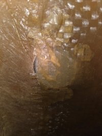
Second question is why is the slug so unbalanced. Kenneth pointed out these are not centered. My guess is it was installed backward. the borescope picture shows it protrudes much further to one side and and angle of the slug doesn't match the angle of the bulkhead/knee.
so, what should you do to fix it? The backing block would be a big project and it would be difficult to source parts, I would just accept the slight misalignment unless there's another reason to replace the block like corrosion or some other mechanical failure. for the main issue that the surveyor identified, I would just disassemble it, flip the slug around, and reassemble. It would also be a good time to chase the threads in the slug and on the tie rod. This cleans them up and allows the tie rod to turn easier. If the slug still doesn't fully engage the plywood, take the slug to a machine shop and ask them to replicated it, but make it a little longer. This would be a very simple part to manufacture.
If you end up wanting to or needing to replace the backing block, I might be able to help out or at least save you some time.
Chainplate Inspection [Master Thread]
Note that for our boat I buffed the stern plate to a mirror finish when it was off the boat. Same for deck shroud connectors and the more-complicated bow fitting. This made inspection easy and should stave off surface corrosion for lots of years. Hopefully. Thanks again for great postings with...
From your pictures, it looks like there's a couple different factors here.
The U-bolt backing plates are built with a predetermined angel that the tie rod exits the block. On our 35-3 this angle wasn't exactly correct which puts some of the tie rods under some longitudinal stress. the 35-3 and 32-2 have a different termination for the tie rods. If our tie rods were terminated the same way, the resulting effect would be pushing the aluminum slug back.
Second question is why is the slug so unbalanced. Kenneth pointed out these are not centered. My guess is it was installed backward. the borescope picture shows it protrudes much further to one side and and angle of the slug doesn't match the angle of the bulkhead/knee.
so, what should you do to fix it? The backing block would be a big project and it would be difficult to source parts, I would just accept the slight misalignment unless there's another reason to replace the block like corrosion or some other mechanical failure. for the main issue that the surveyor identified, I would just disassemble it, flip the slug around, and reassemble. It would also be a good time to chase the threads in the slug and on the tie rod. This cleans them up and allows the tie rod to turn easier. If the slug still doesn't fully engage the plywood, take the slug to a machine shop and ask them to replicated it, but make it a little longer. This would be a very simple part to manufacture.
If you end up wanting to or needing to replace the backing block, I might be able to help out or at least save you some time.
Dave G.
1984 E30+ (SOLD)
Interesting that it is not glassed into place. Pretty sure that is why it has shifted as the encapsulated end is what keeps it in place. There is a whole lot of flexing in any boat and as the shrouds tighten and loosen tack to tack it would definitely move without a "stopper". I would want to get that back to center as much as possible. If access to that area is limited I would do as others suggested and try holding it in place with spacer on the tierod up against the bulkhead. Piece of thick rubber wedged or zip tied to the rod maybe ?
Drewm3i
Marine Surveyor
So far I see nothing of immediate concern. I also agree with the member who said it looks like it was installed backwards--my guess would be from the factory, as people don't usually take these apart even when doing rigging. Boat manufacturers get all sorts of things mixed up on the assembly line, with surprisingly benign results most of the time.
If the part has plenty of wood and glass too grip onto (1" or more), I would likely leave it. If it does not, I would simply reverse it as has been suggested.
If the part has plenty of wood and glass too grip onto (1" or more), I would likely leave it. If it does not, I would simply reverse it as has been suggested.
Doesn’t move at all. Will report back after I’ve tried loosening the turnbuckle above.Does the threaded rod move when you yank on it in different directions/orientations?
Interesting theory. Since there is no access to the end of the deadman that is not glassed in—except for the 5/8” hole I drilled for the scope—how are you thinking they might have removed it for inspection?comparing the original photo to the other ones in the thread, it looks like the glass matt was removed at some point to provide access to the slug. My guess is it was removed to inspect then installed backward.
So, might adjusting the angle of the tie rod below actually put stress on the backing plate and the u-bolt? How much wiggle room is there in the angle predetermined by the backing plate above?From your pictures, it looks like there's a couple different factors here.
The U-bolt backing plates are built with a predetermined angel that the tie rod exits the block. On our 35-3 this angle wasn't exactly correct which puts some of the tie rods under some longitudinal stress. the 35-3 and 32-2 have a different termination for the tie rods. If our tie rods were terminated the same way, the resulting effect would be pushing the aluminum slug back.
I think you may be right about it being in backward—or perhaps the the threaded hole for the tie rod was way off center to begin with. It is definitely true that there is more length to the deadman in front of the tie rod than behind it. In regard to the angle, I think this image really distorts the actual situation.Second question is why is the slug so unbalanced. Kenneth pointed out these are not centered. My guess is it was installed backward. the borescope picture shows it protrudes much further to one side and and angle of the slug doesn't match the angle of the bulkhead/knee.
To disassemble it, I would need to grind off the glass that nearly covers the aft end, since there is no access to the forward end of the cylinder, where there is no glass restricting its movement. Assuming I could then get the deadman to pull out from the aft side, I would then want to glass that end back in. . .So, what should you do to fix it? The backing block would be a big project and it would be difficult to source parts, I would just accept the slight misalignment unless there's another reason to replace the block like corrosion or some other mechanical failure. for the main issue that the surveyor identified, I would just disassemble it, flip the slug around, and reassemble.
Agreed.It would also be a good time to chase the threads in the slug and on the tie rod. This cleans them up and allows the tie rod to turn easier. If the slug still doesn't fully engage the plywood, take the slug to a machine shop and ask them to replicated it, but make it a little longer. This would be a very simple part to manufacture.
Thank you so much, Nick.If you end up wanting to or needing to replace the backing block, I might be able to help out or at least save you some time.
So, might adjusting the angle of the tie rod below actually put stress on the backing plate and the u-bolt?
Yes it would and does, but it's more of a factor of the backing plate being off. You you don't have much room to change where it attaches to to the hull. The only movement is longitudinally and its bound by opening in the TAFG. The angle in the dead man would also have to be drilled correctly. Any misalignment would put stress on the backing plate, rod, and dead man.
How much wiggle room is there in the angle predetermined by the backing plate above?''
I didn't measure, but I would guess only a few degrees. I was surprised how far off mine were.
To disassemble it, I would need to grind off the glass that nearly covers the aft end, since there is no access to the forward end of the cylinder, where there is no glass restricting its movement. Assuming I could then get the dead man to pull out from the aft side, I would then want to glass that end back in. . .

I'm getting confused, is this a different angle of the photo above?

It looks like a different dead man. The first photo looks like someone had already ground off the glass covering the hole, the second one looks like it hasn't been touched. If the first one is the correct photo, you should be able to slide the dead man back and remove it from the inspection port.
These chainplates were a standard system offered by Navtec. Looking at Rig Rite's page, the dead man is called a tie rod nut:
It's made out of anodized aluminum and the rod is made out of Nitronic 50
Yes it would and does, but it's more of a factor of the backing plate being off. You you don't have much room to change where it attaches to to the hull. The only movement is longitudinally and its bound by opening in the TAFG. The angle in the dead man would also have to be drilled correctly. Any misalignment would put stress on the backing plate, rod, and dead man.
How much wiggle room is there in the angle predetermined by the backing plate above?''
I didn't measure, but I would guess only a few degrees. I was surprised how far off mine were.
To disassemble it, I would need to grind off the glass that nearly covers the aft end, since there is no access to the forward end of the cylinder, where there is no glass restricting its movement. Assuming I could then get the dead man to pull out from the aft side, I would then want to glass that end back in. . .
I'm getting confused, is this a different angle of the photo above?
It looks like a different dead man. The first photo looks like someone had already ground off the glass covering the hole, the second one looks like it hasn't been touched. If the first one is the correct photo, you should be able to slide the dead man back and remove it from the inspection port.
These chainplates were a standard system offered by Navtec. Looking at Rig Rite's page, the dead man is called a tie rod nut:
It's made out of anodized aluminum and the rod is made out of Nitronic 50
While I like the "slide the deadman out and flip it the other direction" theory, I won't be surprised if you find you're not able to move the dead man even with no tension on the tie-rod. Here's a competing theory about what could be going on: Perhaps the deadman IS properly positioned through BOTH the fiberglass and plywood in both directions, but, for reasons unrelated, a second piece of plywood was sistered onto the original, aft-facing piece of plywood (face-to-face). If so, what you are seeing in the surveyor's photo is not the deadman end itself, but the glassed-over end of the deadman in the first layer of plywood. If a second plywood piece was added, it makes sense that it would be "duplicate piece", pre-cut to shape and pre-drilled with the gusset hole.
Observations that support this:
1) It appears that both ends of the deadman cylinders have moderate chamfers or bevels around their circumferences. The beveled edge is what makes them look like tubes vs solid cylinders at certain camera angles. That's clearly not what's shown in the surveyor's photo.


2) The green "disc" shown in the surveyors photo does have the same greenish tint that the glassed-over deadman end (or even just the glassed-over plywood) has.
3) The end of every deadman I was able to see in my boat has the ends that are cut squarely with the cylinder walls, resulting in a beer-can shape (both the chamfer/bevel and the square-cut ends can be seen in Christian's photo in post #4). But, your borescope photo shows the forward end of the deadman with a miter-angle that roughly matches the angle of the bulkhead wall in front of the deadman. There is no other location where a miter cut end would be desired, so this argues against your forward deadman being installed backwards.
Good luck on your continued sleuthing.
Observations that support this:
1) It appears that both ends of the deadman cylinders have moderate chamfers or bevels around their circumferences. The beveled edge is what makes them look like tubes vs solid cylinders at certain camera angles. That's clearly not what's shown in the surveyor's photo.
2) The green "disc" shown in the surveyors photo does have the same greenish tint that the glassed-over deadman end (or even just the glassed-over plywood) has.
3) The end of every deadman I was able to see in my boat has the ends that are cut squarely with the cylinder walls, resulting in a beer-can shape (both the chamfer/bevel and the square-cut ends can be seen in Christian's photo in post #4). But, your borescope photo shows the forward end of the deadman with a miter-angle that roughly matches the angle of the bulkhead wall in front of the deadman. There is no other location where a miter cut end would be desired, so this argues against your forward deadman being installed backwards.
Good luck on your continued sleuthing.
Last edited:
Well, here's the update, finally. We're still on the hard, but the cover is off and the weather was mild today (60 degrees, westerly breeze less than 10 knots).
First, I loosened the backstay, four full turns on the hydraulic backstay.
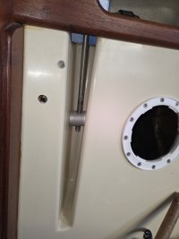
Next, I moved into the salon and loosened the rod on the chain plate in question (forward-most, starboard side). I took it 1/4 turn at a time. After 9 turns (2 1/4 full rotations), it creaked and felt rather loose. I realigned the rod so that it appears centered, which I was able to do with my hands--no additional force required, and then I held the rod in position as I tightened 2.25 rotations.
The rod is now centered (actually a bit more to stern than forward), and the aft end of the deadman is back in position in the plywood, with its aft end sticking out toward the stern, abutting the fiberglass.
All is well.
Now I just have to convince the insurance underwriter that the surveyor just didn't understand the adjustable Ericson chain plate engineering!
Phew!
Thanks for all your great input and support.
First, I loosened the backstay, four full turns on the hydraulic backstay.
Next, I moved into the salon and loosened the rod on the chain plate in question (forward-most, starboard side). I took it 1/4 turn at a time. After 9 turns (2 1/4 full rotations), it creaked and felt rather loose. I realigned the rod so that it appears centered, which I was able to do with my hands--no additional force required, and then I held the rod in position as I tightened 2.25 rotations.
The rod is now centered (actually a bit more to stern than forward), and the aft end of the deadman is back in position in the plywood, with its aft end sticking out toward the stern, abutting the fiberglass.
All is well.
Now I just have to convince the insurance underwriter that the surveyor just didn't understand the adjustable Ericson chain plate engineering!
Phew!
Thanks for all your great input and support.
Attachments
-
 20260415_181706.jpg84.1 KB · Views: 8
 -
 20260415_181721.jpg107.8 KB · Views: 8