Rocinante33
Contributing Partner
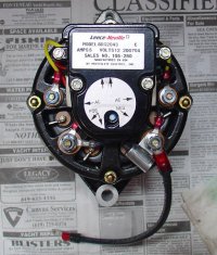
As noted in other threads, I recently upgraded my M25 to a 90 amp marine alternator made by Prestolite, Leece-Neville division. Prestolite is an old, respected name in automotive applications and their Leece-Neville division makes alternators for emergency vehicles, farm & construction equipment and fire trucks, as well as this marine alt. The alt cost me $169 as compared with over $500 for a Balmar plus $100 to $200 for an external regulator. Quite a bit of $avings, IMHO. Please see these URLs for important info on the Prestolite alt;
http://www.prestolite.com/pgs_produ..._id=896&item_series_id=105&refresh=1185927037
http://www.prestolite.com/literature/alts/PP1128_marine.pdf
http://www.prestolite.com/literature/alts/PP1113_AG_Const.pdf
To buy one in your state;
http://www.prestolite.com/pgs_buy/d...ountry_id=2&country_name=USA&province_code=CA
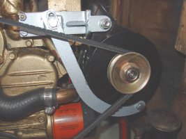
When you buy the alt, don’t forget to get a new pulley. The old alt shaft is a smaller diameter, so is not compatible. The new shaft is 17 mm, which is an unusual size. I got a Delco Remy, part # 10495191, for about $5.
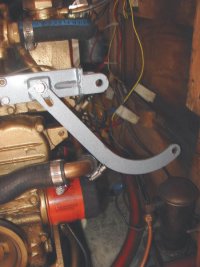
I did the alt bracket upgrade at the same time. It requires draining the coolant from the engine. That bracket upgrade kit now costs $157 from Marine Diesel Direct (up from $98 in '03!). Part# 256891. See
http://shop.torresen.com/ships_store/index.php?mfc=Universal&pn=256891&p=numberresults&storetype=mdd
You might try another source for this; perhaps Engine 1, or Foley’s.
If you do these projects, required readings are the fine thread from Geoff Johnson in '03
http://www.ericsonyachts.org/mainframe.htm
and the link to the Cat*lina owners installation, below. This is a very good description, though I think some of his wiring labels are incorrect.
http://www.pbase.com/mainecruising/catalina_36_alternator
OK. To start the project shut off the batteries, then;
1. I suggest labeling the wires that attach to the back of your existing alt. Most important is to identify the field. It is usually a purple wire. The tach is usually gray. As additional security, a digital picture of your alt may be a good idea for future reference, though not completely necessary.
2. Drain the coolant.
3. Remove the wires and unbolt and remove the alt.
4. The bolt that holds the old bracket in place is probably frozen. It is iron threaded into aluminum. I was unable to get it to release, even with WD40 & an impact driver. Drill the head off of it. Then remove the bracket. Hacksaw the bolt off as close to the engine as possible. The stub of the bolt won't interfere.
5. Review the instruction sheet for the new bracket. Remove the appropriate nuts & studs from the manifold. Coolant will run out if you did not do step 2. I had to use vise grip pliers to remove these studs. Be careful as there is not much thread & the old studs have to come out!
6. Install the new hoses that came with the kit. I had to trim some of them.
7. Install the new studs & bracket loosely. You will need to put ground attachments under a couple of the nuts holding the bracket to the manifold.
8. Try putting the new alt in place. Looks gooooood, huh?
9. My old Motorola alt had two yellow wires attached to a resistor or a diode that was screwed to the bulkhead. It was about 1 1/4" square. Remove it & discard it.
10. Connect the wires. Main output should be at least a 10 ga. wire (red to the starter solenoid ala Tom Meztger's owner’s project). Add a similar sized black wire from the alt ground to the nut on the manifold.
11. The new alt has 2 terminals, each labeled "AC." Connect your field (purple) wire to one and your gray tach wire to the other. Crimp new terminals for each of these wires before connecting.
12. Install the belt. My kit included 2 different sized belts. The smaller barely fit with great effort. The larger was too loose. Snug the belt on the pulley and tighten the pulley retaining nut. The armature can be held with an allen wrench while tightening this nut.
13. Tighten everything up.
14. Add new coolant 50/50 with DI H2O.
15. Double check wiring. No hot wires touching ground!
16. Start her up! Check for leaks. Check for tach function. Check alt output with a digital voltmeter. I see 13.6v at idle, increasing to 14.5v with more RPM.
OK. I will supply pictures in a separate post.


