Existing Garmin N2K setup - no terminator on plotter end?

southofvictor

Member III
Blogs Author
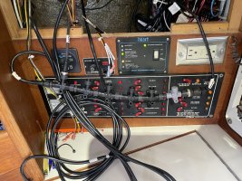
I’m doing more rats nest cleaning and pulled my N2K backbone out from behind the panel. This looks curious to me. One end of the backbone has the wind instrument and an in-line terminator which I believe is correct.

The other has the plotter attached to the male end of the tee and the sounder to the normal drop cable attachment. Is there any reason that this could be correct?

I don’t have any major problems with the network. Only recurring issue is that the VHF loses our GPS position pretty regularly.

Our Garmin environment is pretty old but I’d like to keep it going. Here’s what we have on N2K:

GPSmap 4208
GWS 10
GMI 10
VHF 300
Airmar Tri Multisensor
Em-trak B954 AIS (new)

Pic attached. I’ve stripped off the power cable and all the drops except the ones in question.
 

Attachments

  • IMG_0896.jpeg
    IMG_0896.jpeg
    337.8 KB · Views: 19

southofvictor

Member III
Blogs Author
I just remembered I have a piece at the mast head too. I think what’s in the backbone pic is a lightning arrestor. I think my in line terminator is at the mast head.

1717203509757.jpeg
 

Marlin Prowell

E34 - Bellingham, WA
That is definitely a Garmin in-line terminator at the top of the mast, presumably connected to your GWS 10. Search images for “Garmin in-line terminator” to verify this. So the other terminator should be at the other end of the chain of T-connectors. Looking at your other photo, it looks like the anemometer is connected to the right side of the T-connector chain, and right next to it is another in-line terminator. Move that gray in-line terminator to the other end of the T-connector chain and the network should work much better.
 

southofvictor

Member III
Blogs Author
Followup on this. I think the chartplotter must have a terminator integrated because I get the 60 ohms resistance between blue and white. Voltages all look good.

I get a high resistance between the drain and the negative main bus though. My n2k negative and drain route to a negative bus behind the panel, then to the panel negative bus, then to the negative main bus through an on-off switch. Resistance between the drain and negative at the connector is 0.2 ohms, at the negative bus behind the panel it’s 0.5 ohms, at the panel bus it’s 16 ohms, and at the negative main bus it’s 45 ohms. Nigel Calder says it should be <5 ohms at the negative main bus which would mean there’s way too much resistance in the negative path, correct? Am I looking at this correctly?

Marlin I think the grey tee is a lightning arrestor.
 

Marlin Prowell

E34 - Bellingham, WA
Marlin I think the grey tee is a lightning arrestor.
You are right. Never heard of a NMEA 2000 lightning arrester before, but the GWS 10 installation manual lists it in the parts list. It looks just like an in-line terminator, but is gray.

Measuring 60 ohms resistance between your NMEA 2000 data wires is the correct value. But no NMEA 2000 device will have a built-in terminator because that would put the backbone terminator at the wrong end of a drop cable. If you disconnect the chart plotter from the NMEA 2000 backbone, does the data bus resistance change?

The leftmost tee connector has a cable that is attached to its left connector. This cable is part of your backbone. Where does that go?
 

southofvictor

Member III
Blogs Author
You are right. Never heard of a NMEA 2000 lightning arrester before, but the GWS 10 installation manual lists it in the parts list. It looks just like an in-line terminator, but is gray.

Measuring 60 ohms resistance between your NMEA 2000 data wires is the correct value. But no NMEA 2000 device will have a built-in terminator because that would put the backbone terminator at the wrong end of a drop cable. If you disconnect the chart plotter from the NMEA 2000 backbone, does the data bus resistance change?

The leftmost tee connector has a cable that is attached to its left connector. This cable is part of your backbone. Where does that go?
That cable is labeled chart plotter. I haven’t found anything other than the cable leading to my pedestal guard. If it’s a backbone cable then my guess is that there’s a tee with a terminator in the nav pod.

My Seaview nav pod has security hex head screws holding it together. I need to find a hex key with a hole to open it up. I’ll follow up on resistance reading to make sure it varies when I unplug the plotter cable.

Question - is there any physical difference between a backbone cable and a drop cable? Or is it just where they’re plugged in? I notice Garmin now sells backbone/drop cables and Ancor looks like it sells a drop cable and a
backbone cable as different items.

Thanks for your help Marlin, I appreciate it!
 

Marlin Prowell

E34 - Bellingham, WA
The NMEA 2000 standard says that both backbone and drop cables use 22 AWG wires, so backbone annd drop cables are identical. The only difference is how they are used. Drop cables cannot be longer than 6 meters. The total backbone length cannot exceed 100 meters.

The next level to determining correct network functionality is to calculate voltage drop and this gets involved. In general, any network we install on our boats won’t need more than the standard NMEA 2000 cables. I think Maretron started it, and now I see Ancor is also upselling us on higher capacity backbone cables. The Maretron “mid” cables are 16 AWG for the two power wires and 20 AWG for the two data wires and shield. But these are only necessary on big boats with lots and lots of devices.

Your particular network is interesting. The cable up the mast is a NMEA 2000 cable, used as a backbone. It’s too long a distance for a drop cable, so you have to have the network backbone run up the mast. Garmin did this correctly, providing a backbone terminator at the end, at the top of the mast.

Likewise, it seems that the cable to the chart plotter is also a backbone cable and there is undoubtably a terminator at the end, inside your Seaview nav pod. If you add a devices to your network, it must be done at your chain of Tee connectors that are in the middle. You need to ensure that your chartplotter and wind cables remain as backbone cables because moving your backbone terminators to somewhere else is challenging.
 

southofvictor

Member III
Blogs Author
Likewise, it seems that the cable to the chart plotter is also a backbone cable and there is undoubtably a terminator at the end, inside your Seaview nav pod. If you add a devices to your network, it must be done at your chain of Tee connectors that are in the middle. You need to ensure that your chartplotter and wind cables remain as backbone cables because moving your backbone terminators to somewhere else is challenging.
Thanks Marlin!

I double checked this morning and yes, when I remove the chart plotter cable I get 120 ohms and when I plug it back in I get 60.
 
Top