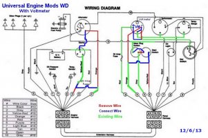
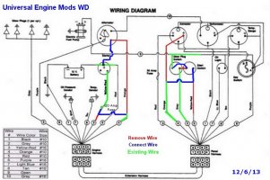
Because the archives are currently not available, here are Tom Metzger's
notes on upgrades and recommended changes to Universal diesel wiring:
UNIVERSAL DIESEL WIRING MODIFICATIONS
During discussions on the Sailnet Ericson e-mail list about wiring problems with
Universal diesel engines someone asked if it would be possible to write a wire by wire
description of the changes we were talking about. I have endeavored to do that here.
Change “A” increases the battery charging current from the alternator by reducing the
length of the wire between the alternator and the battery.
Change “B” eliminates a common problem with Universal diesel engines, that being
insufficient power at the starter solenoid to start the engine. Increasing the wire size will
resolve the problem and may extend the life of the starter switch as the contacts get dirty.
Change “C”, which is not labeled on the wiring diagram but is shown there, uncouples
the starter switch from the glow plug switch. This allows you to start the engine without
holding in the glow plug switch. This is a convenience because the engine retains
enough heat to start without glow plugs for several hours after being shut down.
April 25, 2001
MODIFICATIONS
Turn the battery switch to “Off” before disconnecting any wires.
Change “A”: This change connects the alternator output directly to the solenoid battery
connection without going to the engine instrument panel and back again. The ammeter on the
instrument panel will only read the current going to the engine components (glow plugs, starter
solenoid, fuel pump, blower, panel lights, and instruments. This is useful for troubleshooting if
the engine has starting problems.
1. Disconnect the orange wire from the ammeter terminal on the panel.
2. Disconnect the other end of the orange wire from the alternator output terminal.
3. Install 2 new #10 wires, or one #6 or #8 wire, between the alternator output terminal and
the solenoid power terminal. There is already a large (1/0) red wire on this solenoid
terminal coming from the battery switch common terminal. [If you install a larger
alternator this new wire should be #2 or larger. You should also add a black wire of the
same size from the alternator ground terminal to the engine and battery connection point.]
4. If not doing change “B” tape both ends of the orange wire to prevent short circuits and to
keep the wire from flopping around.
Change “B”: This change replaces the #16 wire between the “Start” switch and the starter
solenoid. This small wire has caused starting problems in the past for many boaters.
1. Remove the yellow-red wire from the terminal of the starter solenoid.
2. Remove the fuse holder from the yellow-red wire or purchase a new fuse holder with 20
amp fuses.
3. Connect the fuse holder to the orange wire disconnected in step 2 in change “A”.
4. Connect the fuse holder to the now empty terminal on the solenoid.
5. Remove the yellow-red wire from the starter switch.
6. Connect the other end of the orange wire to the now vacant terminal of the starter switch.
7. Tape both ends of the yellow-red wire to prevent short circuits and to keep the wire from
flopping around.
Change “C” Shown, but not labeled on wiring diagram: This change has already been made on
many engine panels. It changes the starter circuit so that the glow plug push button does not
have to be pushed to operate the starter push button. It is primarily a convenience, but may
extend the life of the glow plug switch.
1. Disconnect the gray (?) jumper from the starter switch on the glow plug switch and
reconnect it to the other terminal of the glow plug switch. There is already a purple wire
on this terminal.
Put the changes that you make into your owner’s manual so the next owner doesn’t bad mouth
the PO.
Tom Metzger
2/11/01
Ammeter replacement
To replace the panel ameter with a voltmeter.
Connect the lamp wire from the ammeter to the lamp connection on the VM if there is one. If not the end of the wire should be taped so it cannot touch anything else and secured so it is not loose.


And still more excellent reading on the subject here:
http://forums.catalina.sailboatowners.com/showthread.php?t=135558
http://c34.org/bbs/index.php/topic,5078.0.html
notes on upgrades and recommended changes to Universal diesel wiring:
UNIVERSAL DIESEL WIRING MODIFICATIONS
During discussions on the Sailnet Ericson e-mail list about wiring problems with
Universal diesel engines someone asked if it would be possible to write a wire by wire
description of the changes we were talking about. I have endeavored to do that here.
Change “A” increases the battery charging current from the alternator by reducing the
length of the wire between the alternator and the battery.
Change “B” eliminates a common problem with Universal diesel engines, that being
insufficient power at the starter solenoid to start the engine. Increasing the wire size will
resolve the problem and may extend the life of the starter switch as the contacts get dirty.
Change “C”, which is not labeled on the wiring diagram but is shown there, uncouples
the starter switch from the glow plug switch. This allows you to start the engine without
holding in the glow plug switch. This is a convenience because the engine retains
enough heat to start without glow plugs for several hours after being shut down.
April 25, 2001
MODIFICATIONS
Turn the battery switch to “Off” before disconnecting any wires.
Change “A”: This change connects the alternator output directly to the solenoid battery
connection without going to the engine instrument panel and back again. The ammeter on the
instrument panel will only read the current going to the engine components (glow plugs, starter
solenoid, fuel pump, blower, panel lights, and instruments. This is useful for troubleshooting if
the engine has starting problems.
1. Disconnect the orange wire from the ammeter terminal on the panel.
2. Disconnect the other end of the orange wire from the alternator output terminal.
3. Install 2 new #10 wires, or one #6 or #8 wire, between the alternator output terminal and
the solenoid power terminal. There is already a large (1/0) red wire on this solenoid
terminal coming from the battery switch common terminal. [If you install a larger
alternator this new wire should be #2 or larger. You should also add a black wire of the
same size from the alternator ground terminal to the engine and battery connection point.]
4. If not doing change “B” tape both ends of the orange wire to prevent short circuits and to
keep the wire from flopping around.
Change “B”: This change replaces the #16 wire between the “Start” switch and the starter
solenoid. This small wire has caused starting problems in the past for many boaters.
1. Remove the yellow-red wire from the terminal of the starter solenoid.
2. Remove the fuse holder from the yellow-red wire or purchase a new fuse holder with 20
amp fuses.
3. Connect the fuse holder to the orange wire disconnected in step 2 in change “A”.
4. Connect the fuse holder to the now empty terminal on the solenoid.
5. Remove the yellow-red wire from the starter switch.
6. Connect the other end of the orange wire to the now vacant terminal of the starter switch.
7. Tape both ends of the yellow-red wire to prevent short circuits and to keep the wire from
flopping around.
Change “C” Shown, but not labeled on wiring diagram: This change has already been made on
many engine panels. It changes the starter circuit so that the glow plug push button does not
have to be pushed to operate the starter push button. It is primarily a convenience, but may
extend the life of the glow plug switch.
1. Disconnect the gray (?) jumper from the starter switch on the glow plug switch and
reconnect it to the other terminal of the glow plug switch. There is already a purple wire
on this terminal.
Put the changes that you make into your owner’s manual so the next owner doesn’t bad mouth
the PO.
Tom Metzger
2/11/01
Ammeter replacement
To replace the panel ameter with a voltmeter.
- Put the red #10 wire from the ammeter on the VM positive stud.
- Put the orange (?) wire from the ammeter that goes to the key switch on the same positive VM stud with the red wire. If the ammeter voltmeter swap is the only change you are making then you should move both of the orange wires to the positive VM stud.
- Put the black wire from the ammeter ground stud on the VM negative stud and jumper to the ground stud for the lamp if there is a lamp and/or ground stud. If there was no lamp in the ammeter you will have to find a ground point on the panel and run a small black wire to the VM negative stud. There is virtually no current so any size black wire will do.
Connect the lamp wire from the ammeter to the lamp connection on the VM if there is one. If not the end of the wire should be taped so it cannot touch anything else and secured so it is not loose.


And still more excellent reading on the subject here:
http://forums.catalina.sailboatowners.com/showthread.php?t=135558
http://c34.org/bbs/index.php/topic,5078.0.html
Last edited:


![Alternator 003A [800x600].JPG Alternator 003A [800x600].JPG](https://ericsonyachts.org/ie/data/attachments/10/10749-18938ac91c3d95d91307e71e782f33d1.jpg)