Guest viewing is limited
- You have a limited number of page views remaining
- 19 guest views remaining
- Register now to remove this limitation
You are using an out of date browser. It may not display this or other websites correctly.
You should upgrade or use an alternative browser.
You should upgrade or use an alternative browser.
off season charging batteries onboard with a solar panel
- Thread starter hdlEric
- Start date
If ALL the batteries are wired in parallel then you only have one battery "bank" which would make the battery switch just an on-off switch (versus a battery selector).The batteries are wired in parallel.
How many banks do you have? Are you trying to charge more than one bank with solar?
Slick470
Sustaining Member
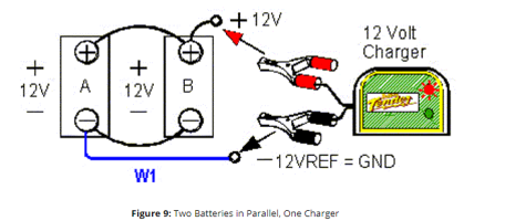
For two batteries in parallel, you would normally connect to the positive connection on one battery and to the negative on the other battery. Like this:

For a 100A solar panel, you'll also want a charge controller. They generally come in two varieties, MPPT or PWM. MPPT is better, but will cost more. Several brands make quality ones, Genasun and Victron Energy seem to be the ones I see recommended the most. Pick the one that matches your battery chemistry/panel wattage/output amp/feature set. Adding in an inline fuse on the positive side is usually a good practice too.
For your battery switch, you'd be wiring directly to the battery posts, so switch position won't matter. Some people will add in an inline switch between the charge controller and the battery to shut off the charging if desired.
You didn't ask, but if you were doing two bank charging from a single panel, you'll could do the above and then add in a combiner between the two banks. Blue Seas and Yandina make quality stuff. They basically let the first bank charge, and then will close a one way circuit to the 2nd bank to allow it to charge as well.
Yes, I do have a shore power charger on board, but I presently don't know how it is wired to the battery bank.Ok, that is easier. Also, do you have a shore-power (AC) charger on the boat? Do you know how that is wired to the battery bank?
For two batteries in parallel, you would normally connect to the positive connection on one battery and to the negative on the other battery. Like this:
View attachment 46089
For a 100A solar panel, you'll also want a charge controller. They generally come in two varieties, MPPT or PWM. MPPT is better, but will cost more. Several brands make quality ones, Genasun and Victron Energy seem to be the ones I see recommended the most. Pick the one that matches your battery chemistry/panel wattage/output amp/feature set. Adding in an inline fuse on the positive side is usually a good practice too.
For your battery switch, you'd be wiring directly to the battery posts, so switch position won't matter. Some people will add in an inline switch between the charge controller and the battery to shut off the charging if desired.
You didn't ask, but if you were doing two bank charging from a single panel, you'll could do the above and then add in a combiner between the two banks. Blue Seas and Yandina make quality stuff. They basically let the first bank charge, and then will close a one way circuit to the 2nd bank to allow it to charge as well.
Yeah, like Slick470 said, but I'd emphasize the part about definitely adding a fuse to the positive solar lead, and keeping the fuse near the battery.
Also, not related to your solar question, but if you don't have one, it's wise to add a 150-200A MRBF fuse between the battery and batt cable too. And, Ericson likely didn't fuse the shore power charging leads either, so, once you find those, consider fusing them too.

Also, not related to your solar question, but if you don't have one, it's wise to add a 150-200A MRBF fuse between the battery and batt cable too. And, Ericson likely didn't fuse the shore power charging leads either, so, once you find those, consider fusing them too.

Last edited:
Thanks Kenneth for the info! The fuse block looks like a good investment.Yeah, like Slick470 said, but I'd emphasize the part about definitely adding a fuse to the positive solar lead, and keeping the fuse near the battery.
Also, not related to your solar question, but if you don't have one, it's wise to add a 150-200A MRBF fuse between the battery and batt cable too. And, Ericson likely didn't fuse the shore power charging leads either, so, once you find those, consider fusing them too.
View attachment 46092
Frank Langer
1984 Ericson 30+, Nanaimo, BC
Kenneth
I generally understand the need for a fuse in a 10,12 or 14 gauge wire leading to a pump, where the motor could seize and draw lots of current, so fuses provide protection. But I don't really understand why a fuse is needed at the battery terminal if the terminal is clean/tight and the heavy battery wire (2 gauge, I think) goes to the battery switch and to the starter motor all with clean tight connections. Can you please explain, as I'm always still learning.
Frank
I'm a DYI'er, not a marine electrician so this is just my opinion, but fuses are typically to protect wires from overheating (and causing fires) caused by short circuits. Your scenario of a motor seizing is a good example. Shorts could also be caused by wire chafing, a ball of aluminum foil that misses the trash can and ends up bridging the contacts of a battery charger [that's where my original charger was located], dropped tools, or many other possible scenarios Murphy may dream up.
When I got my boat, the large (1/0) cable serving my start battery was literally draped over one sharp corner of the aluminum fuel tank, then snugged up against the copper fuel line and the aluminum motor mounts. Often times our battery cables are run through compartments where visual inspection is difficult.
I suppose if you KNOW, your cables are chafe protected, in good condition, secured by metal P-clips where suspended, and attached with clean, tight, and shielded terminals, then you may have a pretty strong argument that shorting is unlikely. If not, fuses are pretty cheap insurance.
Last edited:
Frank Langer
1984 Ericson 30+, Nanaimo, BC
I'm a DYI'er, not a marine electrician so this is just my opinion, but fuses are typically to protect wires from overheating (and causing fires) caused by short circuits. Your scenario of a motor seizing is a good example. Shorts could also be caused by wire chafing, a ball of aluminum foil that misses the trash can and ends up bridging the contacts of a battery charger [that's where my charger was located], dropped tools, or many other possible scenarios Murphy may dream up.
When I got my boat, the large (1/0) cable serving my start battery was literally draped over one sharp corner of the aluminum fuel tank, then snugged up against the copper fuel line and the aluminum motor mounts. Often times our battery cables are run through compartments where visual inspection is difficult.
I suppose if you KNOW, your cables are chafe protected, in good condition, secured by metal P-clips where suspended, and attached with clean, tight, and shielded terminals, then you may have a pretty strong argument that shorting is unlikely. If not, fuses are pretty cheap insurance.
Thanks, that's helpful!
Frank
gareth harris
Sustaining Member
When connecting a battery to charge long term it is critical that the voltage is not too high. If your batteries are lead acid (lithium have different needs), then the solar cell will need to be connected via a three stage charger which will set the voltage using an electronic battery sensor. The first of the three stages is applied when the battery is significantly discharged, and the charging voltage is set at about 14.4V - 14.6V so that most of the 100W from the solar cell goes into the battery. As the level of charge reaches about 80% the second stage takes over and sets the voltage to about 14.2V so that hydrogen does not start to vent from the battery. As the battery reaches about 95% charge the third stage sets the charging voltage to about 13.2V, which keeps the battery topped up without overcharging.
Wiring it is pretty straightforward, if the batteries are in parallel rather than separated by a selector switch then it just takes the two connections as Slick has described.
The charger will need enough space around it to dissipate heat, 100W is not a lot but if a bag of your belongings falls on top of it it will overheat.
Gareth
Freyja E35 #241 1972
gareth harris
Sustaining Member
It never used to be standard practice to fuse a starter circuit since the currents involved are huge, however sailboat engines are small enough for it to be feasible and I put a 100A circuit breaker next to my battery which was enough to start my A4.Kenneth
I generally understand the need for a fuse in a 10,12 or 14 gauge wire leading to a pump, where the motor could seize and draw lots of current, so fuses provide protection. But I don't really understand why a fuse is needed at the battery terminal if the terminal is clean/tight and the heavy battery wire (2 gauge, I think) goes to the battery switch and to the starter motor all with clean tight connections. Can you please explain, as I'm always still learning.
Frank
I did so after an incident when I tried to go sailing with ongoing work cluttering the cabin, and as I was rigging I heard the engine start turning by itself as the cabin filled with smoke. A piece of 14AWG wire had come loose and its end had contacted the engine block so it that shorted, and it had melted its way through a 2AWG cable to the engine which sent power into the starter.
Gareth
Freyja E35 #241 1972
I deeply appreciate everyone's time and input, but I am not an electrician neither, and maybe I am being to cheap or this is beyond my skill level. I bought a 100W solar cell, and voltage regulator from Harbor Freight, and wanted to hook it directly to the 2 batteries to keep them charged over the Winter. Is this possible??
Frank Langer
1984 Ericson 30+, Nanaimo, BC
Hi,I deeply appreciate everyone's time and input, but I am not an electrician neither, and maybe I am being to cheap or this is beyond my skill level. I bought a 100W solar cell, and voltage regulator from Harbor Freight, and wanted to hook it directly to the 2 batteries to keep them charged over the Winter. Is this possible??
I think Slick470 answered this for you in post #5 above, indicating that you will need a controller to avoid overcharging your batteries, if I have understood correctly.
Frank
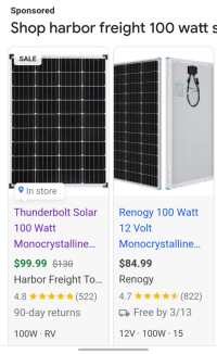
No experience with the Harbor Freight solar stuff, but it wouldn't be my first choice. Just found this:
HFT Thunderbolt 100W solar panel: $99.99
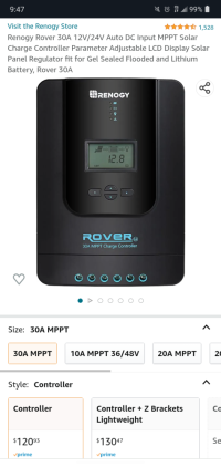
HFT Thunderbolt 30A charge controller $76.99
VS
Renogy 100W Solar panel: $84.99
Renogy Rover 30A MPPT controller: $120.99
Renogy is quality stuff. I used Renogy panels and Victron controllers, but I see Victron's prices have gone up a lot since I bought mine.


Last edited:
Thanks FrankHi,
I think Slick470 answered this for you in post #5 above, indicating that you will need a controller to avoid overcharging your batteries, if I have understood correctly.
Frank
Jerry VB
E32-3 / M-25XP
As mentioned previously, Slick470's diagram is what you want to do, except you have a solar charger rather than an AC charger (plugs into the solar panel rather than the wall plug).I bought a 100W solar cell, and voltage regulator from Harbor Freight
I assume you bought the...
The solar panel has an output plug that plugs directly into the charge regulator "solar" plug pigtail. That should be easy unless you need to extend the wire - if you do, make SURE you don't inadvertently reverse the polarity (don't cross the streams).
You will need to source a compatible plug for the battery and run a pair of wires from the solar charger plug to your batteries, putting a fuse (10A should be good) close to the batteries. In Slick470's diagram, this would be the alligator clips (you can use alligator clips if you want a temporary connection - still fuse it!). Make sure the + (red) side of the battery output plug goes to the + post on the battery!
Safely terminate the "Load" outputs so they don't short to each other or to anything else (heat shrink is good). Alternatively, you could connect the "load" output to e.g. a lighter plug. It isn't obvious whether the "load" output is powered by the battery when the solar isn't charging (probably). If it is powered by the battery, make sure you don't connect a load that could discharge the battery if it doesn't get enough sun.
This isn't a fancy multistage charge controller but it should keep your batteries topped off without boiling them.
