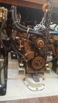
The broken part has been removed. It is made up of 6 individual steel parts welded together. The middle weld at the break was nothing more than a tack weld, with no penetration of the component parts. The engine was installed in my 1987 32-3 in 2020, less than a year before I bought it. I'm pretty sure this piece was broken pretty much from the time I bought the boat, but I have had no issues that I would attribute to a broken mount. The engine was only 1/16" lower at the location of the break, as the engine block overhangs the mount location, so the block was
still getting support from the vibration isolator.
I have yet to decide what to do from here. I could order a new mount from Westerbeke, but if it is the same design as the original, I would be concerned about reliability. Further, installation of a new piece could be a challenge: the rectangular cutouts in the horizontal plate at the bolts are not quite long enough for a socket to fit on the bolt head. A shorter than normal socket would be needed in order to get full torque in tightening the bolts.
Another option would be to repair and improve the part that I have. In that case, I would consider moving the horizontal plate lower on the vertical plate at the engine block, so as to not restrict use of a normal socket on the upper bolts. I would also want to consider an additional vertical gusset below and perhaps also above the horizontal plate. The horizontal plate could be lowered 1/2" easily, as there is a bit more than 3/4" of stud between the top of the vibration isolator and the bottom of the horizontal plate.
Yet another option would be for fabrication of a new mount, with at least some of the improvements described above.
All comments, corrections and insights welcome. I especially would like to hear from
@Kenneth K and
@Pete the Cat since they seem to know how to deal with this sort of thing
")
.
View attachment 55151
View attachment 55152
View attachment 55153