E-32-2 Electrical Overhaul

Tin Kicker

Sustaining Member
Moderator
Just getting back to the boat today to take some photos of what I’m dealing with - if only for entertainment value.

Keeping the bilge blower as a safety makes sense to me for the moment - although I don’t think I’ve ever actually used it. If it ever failed I don’t know that I could justify the cost of replacement. But then again, if I never use it it will never fail, right?

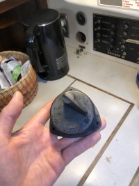
I also pulled the air filter from my engine and attached a photo of what I’m dealing with - I do like the idea of replacing it with a K&M. I’ll get one on order.

The air filter should definitely go, just because it's so inefficient and replacing it is inexpensive for the improvement.

Your wiring could be better organized but is comparatively not that bad. It does look like you could install a new face plate to add the circuits you want to and make it look good. Getting faceplates engraved is not terribly expensive if you shop around.

Meanwhile look for potential issues which can stop you or create problems. The boat I have is honestly not bad but I mentioned the choke point right below the C/B panel in the E32-3 yesterday, and below is a photo I took last night. The heavy cable is from the battery and it is chafing/pinching the alternator field wire. To make it even more silly, the battery cable is not in a conduit (PVC tube) so it can rub the fiberglass but a ground cable is.
20200503_180204-X2.jpg


Another typical was unwrapping the trailer connector to cut it out and found why I could not locate the red wire at this end. Somebody butt-spliced in a pink for it and a plain gray for a gray with a tracer. This was all covered by wrapped black tape. The pen is pointing at green corrosion coming from a contact in the trailer connector. Corrosion creates resistance which creates heat. The yellow/red was a recommended mod some time ago, they just didn't bother capping/insulating the end.
20200503_171231-X2.jpg


The fuel quantity wire had three butt splices - and three wire colors - within about 3 feet. It was not functional because one of the splices was corroded. Normal stuff to find and fix in an older boat.
20200503_172458-X4.jpg
 

nquigley

Sustaining Member
//
Meanwhile look for potential issues which can stop you or create problems. The boat I have is honestly not bad but I mentioned the choke point right below the C/B panel in the E32-3 yesterday, and below is a photo I took last night. The heavy cable is from the battery and it is chafing/pinching the alternator field wire. To make it even more silly, the battery cable is not in a conduit (PVC tube) so it can rub the fiberglass but a ground cable is.
20200503_180204-X2.jpg
I (carefully) used a 1" hole saw to cut three overlapping holes into that trough beside the main battery cables when I was running my heavy windlass cables.
I used a rasp, then coarse sandpaper, to make the overlapping holes one nice smooth-edged elongated slot. This extra room was useful when I recently ran wires from the battery box up to the DC panel when I installed a battery monitor (Victron BMV-712).
 

Kenneth K

1985 32-3, Puget Sound
Blogs Author
More on bilge blowers: If you are going to use one, under the premise of removing heat from the engine compartment, check where the open end of the duct is actually drawing air from. Both of my aft dorade vents (one has an inline blower installed) suck air in from the bottom of the under-cockpit area (aft and below the engine compartment). Beneath the waterline and against the hull- they draw air from one of the cooler parts of the boat. The blower would remove more heat if the inlet were run to the top of the engine compartment.

........the .15A 70mm computer fan running in series with it. The current draw is so little that it can be overcast for a week + and a battery still doesn't run down.

.......Two shower drains:

Tin Kicker - you should have patented that before taking it public.
 

Kenneth K

1985 32-3, Puget Sound
Blogs Author

What timing that you post this picture? Just last night, I pulled my starting-battery cable off the battery switch and through that little hole you show. Things were so cramped in the channel below this hole that I first had to remove the battery charger cables to both batteries to make room in the channel to remove the 1/0 cable. Of course, I had to cut the PVC tubing off the cable before I could pull it. The cable was 10.5 feet long, un-tinned, and with a butt splice in the middle of it.

When I put in a new battery charger, I don't think I'm going to run the wires all the way back to the battery switch as they were. That's a long run, and there is already too much going on behind that panel.

Also, can you explain the purpose of the "alternator field wire?" Where does it begin and terminate? I was under the impression that the only "external" alternator wires (mine is the stock 55A Motorola) were the (+)Output, the (-)Gnd, and the "purple wire / alternator excitation" circuit that comes off the engine panel (this is the purple wire shown in your trailer-plug picture).
 

Christian Williams

E381 - Los Angeles
Senior Moderator
Blogs Author
I still need tutoring on this diesel blower thing. Gasoline vapors and propane are heavier than air, therefore evacuation from a low point makes sense.

But how effective is ducting for removing hot air, which rises? The venting tube is probably 4" max.

Wouldn't it move a lot more engine-bay air to install a basic open fan to push hot air toward the cowl vents?

So: what is the purpose in heat removal for vent tubing, which, leaving aside the inevitable restrictions, sags and bends under a cockpit, can only move a limited volume of air.

Why have I never seen an open fan installed in our engine bays, whereas they are popular in the cabin--where nobody would consider a vent-tube system effective at cooling?

Not arguing, just thinking it through.
 
Last edited:

Kenneth K

1985 32-3, Puget Sound
Blogs Author
But how effective is ducting for removing hot air? The venting tube is probably 4" max.

Yeah, I'm not sure I'm sold on the idea of a blower myself. My boat came with one so I left it intact. Good point about a "low-mounted" intake if you're trying to vent gas or propane (IF the blower is "ignition protected", and not just a "fan").

As for moving air, I just replaced a bathroom fan in my house last month. It uses 4" ducting similar to what's in the boat. These bathroom fan/duct systems are typically rated at 80-100 cubic feet per minute, so the 4" duct can still move a lot of air-over time. Opening the lazarrete lid moves a lot of air - instantly.
 

Tin Kicker

Sustaining Member
Moderator
Tin Kicker - you should have patented that before taking it public.

More about using the computer fans:

Neglected to mention that there is a small ON-OFF switch on the electric sub-panel inboard of the quarter berth. That panel also has the terminal strip which took the place of the trailer connector.

Don't have a photo for the fan in the head ceiling but it is even simpler. Pull down the headliner, cut back the plywood about 3/4", and use 4 #6 wood screws. I had to cut the 4 mounting ears off one side of the fan to fit into the hole in the plywood. There's a small switch next to it for quiet nights. I do leave the vent on the dorade box aft to lessen water getting into the dorade.

If mounting the fans horizontally, ball bearings are better than the sleeve bearings mine has. The sleeve bearings in the horizontal orientation cut the life in roughly half. Still the life in these is in the tens of thousands of hours so I'm not too worried.
 

Tin Kicker

Sustaining Member
Moderator
I still need tutoring on this diesel blower thing. Gasoline vapors and propane are heavier than air, therefore evacuation from a low point makes sense.

But how effective is ducting for removing hot air? The venting tube is probably 4" max.

Wouldn't it move a lot more engine-bay air to install a basic open fan to push hot air toward the cowl vents?

So: what is the purpose in heat removal for vent tubing, which, leaving aside the inevitable restrictions, sags and bends under a cockpit, can only move a limited volume of air.

Why have I never seen an open fan installed in our engine bays, whereas they are popular in the cabin--where nobody would consider a vent-tube system effective at cooling?

Not arguing, just thinking it through.

It moves air continuously and any movement beats no movement. More than that to me is that mine is on the suction side so it removes engine/bilge/boat smells from back there.
 

Amontyg

Member I
Another question regarding the blower - I’m assuming the switch pictured is the OEM, and I’d like to replace it to free up room on the panel for the propane switch/sensor.

Does anyone know why this switch was so beefy? Could I replace it with a simple 15 amp toggle?
 

Attachments

  • image.jpg
    image.jpg
    98.6 KB · Views: 18

Tin Kicker

Sustaining Member
Moderator
Another question regarding the blower - I’m assuming the switch pictured is the OEM, and I’d like to replace it to free up room on the panel for the propane switch/sensor.

Does anyone know why this switch was so beefy? Could I replace it with a simple 15 amp toggle?

You should be able to. Look at the fan label for amps, and at the value on the breaker to be sure, but I doubt the blower needs more than 7-10 amps.
 

kapnkd

kapnkd
Another question regarding the blower - I’m assuming the switch pictured is the OEM, and I’d like to replace it to free up room on the panel for the propane switch/sensor.

Does anyone know why this switch was so beefy? Could I replace it with a simple 15 amp toggle?

That old Sudbury switch sure brings back memories. On my, then new, ‘73 E-32 it was located in the cockpit on the engine panel. It didn’t last, the dealer put on another and in short order - it too succumbed to the outdoor salt air environment. I gave up left it in the on position along with the panel blower switch and simply used the interior main battery switch which is also vapor proof.

Reason it was so beefy was for it being vapor proof to prevent any potential spark from igniting any buildup of gasoline fumes.

Not as critical with diesel fuel ...BUT...if one still has a gasoline powered engine, any blowers and switches used need to be safely away and protected from any and all vapor fumes. The tiniest of an electrical spark is all it takes. I really like the computer fan idea but worry about it being a potential for any unwanted sparks.

It should go without saying that any selection of a switch or breaker should be spark proof.
 

1911tex

Sustaining Member
The OEM blower switch on most boats s a simple toggle switch like you suggest.
____________________________________________________________
My OEM blower paddle switch (which I never use, but it works) is on the ignition panel just above the push glow-plug and starter switches. The boat originally came with the current M25, 5421 engine...can't understand why the blower? Maybe I will remove the blower someday and use the switch for an accessory as it is already wired for use?
 

Amontyg

Member I
Thanks for the quick input, the switch has been replaced, and blower tube moved high in the engine compartment.

My next question involves the fuel gauge - mine has never worked, and I can’t seem to find previous posts on how to test the various aspects of that system. I have tested continuity on the wire from the sender to the back of the gauge, tested for 12v at the gauge, as well as testing to make sure the tank is grounded. Is there a way to test whether the gauge or sender is at fault?
 

kapnkd

kapnkd
Thanks for the quick input, the switch has been replaced, and blower tube moved high in the engine compartment.

My next question involves the fuel gauge - mine has never worked, and I can’t seem to find previous posts on how to test the various aspects of that system. I have tested continuity on the wire from the sender to the back of the gauge, tested for 12v at the gauge, as well as testing to make sure the tank is grounded. Is there a way to test whether the gauge or sender is at fault?

Not sure at all - as our “fuel gauge” from the ‘73 era is but a wooden dowel inserted through the filler opening to bottom out and read the level of the wet wood. (It has never once failed me in accuracy.) ;-))
 

Tin Kicker

Sustaining Member
Moderator
Thanks for the quick input, the switch has been replaced, and blower tube moved high in the engine compartment.

My next question involves the fuel gauge - mine has never worked, and I can’t seem to find previous posts on how to test the various aspects of that system. I have tested continuity on the wire from the sender to the back of the gauge, tested for 12v at the gauge, as well as testing to make sure the tank is grounded. Is there a way to test whether the gauge or sender is at fault?

Assuming that you have an electric gauge they are easy to pull and check but first, check the rest of the circuit. The terminal at the center of the sending unit should get 12V. The tab toward which is probably under the head of a mounting screw should have minimal resistance to ground.

The sender is typically held in place with just four sheetmetal screws. Old diesel turned to tar will have glued it in place so you may need a flat blade to get under the gasket. If the gasket is shot you can cut one out of silicone sheet from the local hardware store.

As the air moves up and down the resistance should be between 0-190 ohms or 30-240 ohms, probably the latter. If not, the senders are only about $30 on Amazon.
 
Top