Guest viewing is limited

Electrical Panel Revision

Jim Picerno

1989 38-200
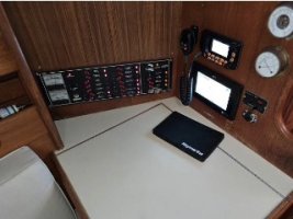
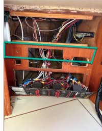
After reading the many posts on the topic of revising the electrical panel, I’ve finally “girded my loins” (at least figuratively) and started working on a plan. As you can see in the photo, my boat has the original electrical panel. There must have been instruments installed directly over the electrical panel that were covered up by the PO with a1/4” sheet of teak veneer. You can see the cutouts where the various instruments previously resided. Removing the veneer panel revealed the rats nest behind the panel.

Here’s my plan. I want to remove some of the old teak surrounding the removed instruments to have a larger opening to work behind the panel (see photo). I think I can put a piano hinge on the teak veneer piece so it can fold down rather than being screwed. During my cursory examination I know I’ve got a number of circuits connected to the electrical panel which are under fused, over fused, or not fused at all. For instance when I turned on the electronics switch the VHF came on even though the VHF switch on the panel was off. My plan is to go thorough the wiring and connect each device to a fused terminal block with the correct fuse. Then run a wire from the terminal block to the panel. I know this is doubling up on the fuses but at least I’ll know that each device is fused correctly downstream from the panel. I could of course do the same thing but replace the panel with just a switch panel, but I’m trying to do the job correctly while not spending a lot of time and money on this, given I’m working on other projects. This plan would also allow me to replace the panel with a switch only panel down the road. I’m also planning on labeling all the wires. To that end I bought this labeler with some of my “Prime” dollars. Quite a big less expensive than a Dymo and the shrink wraps labels I’ve tested so far seem to be okay. Curious to know what folks are doing for a naming convention. My initial thought was numbers put in a spreadsheet matched to a device. In general am I heading down the right path here? Any gotchas I need to be aware of? Thanks.


Attachments

  • Nav Station - Electrical Panel - closed.jpg
    Nav Station - Electrical Panel - closed.jpg
    24.3 KB · Views: 20
  • Electrical Panel - modified.jpg
    Electrical Panel - modified.jpg
    98.2 KB · Views: 20
  • Electrical Panel.jpg
    Electrical Panel.jpg
    77.3 KB · Views: 20

Loren Beach

O34 - Portland, OR
Senior Moderator
Blogs Author
Your are (bravely) way ahead of me. I do have a panel upgrade in the planning stage for this winter, though.
Note that our panel is identical to yours. Ours is still functional, as far as the $$ breakers all working fine, but.... the little "ruby lights" are varying a lot in brightness, and a couple are painfully dim.
I would like to replace them all with modern LED versions and plan to ask the Ericson OEM vendor, https://www.newmarpower.com/ , if they sell upgrade kits.
Please keep up updated on your project.
Thanks!


ps: your boat and ours might have been wired by the same group of "rats"... :rolleyes:
 

peaman

Contributing Partner
Following guidance provided here, I greatly improved the electrical panel on my 1987 32-3. Images below are "before" and "after". In order to clean-up the rat's nest, I mounted two ground strips and two circuit strips to the hull liner within the compartment. All ground wires from circuits connect to the ground strips, including the main ground to the battery negative. All circuit wires running out of the electrical compartment are terminated at one of the two circuit terminal strips. The terminals on the terminal strips correspond exactly to the breakers on the panel for very easy circuit tracing. That arrangement also makes easy the removal of the panel, for example, to replace a circuit breaker or LED lamp. Each circuit wire is labelled on each side of the circuit terminal strip: one label on the wire from the circuit breaker, and another on the wire leading out of the electrical compartment. The labels read same or similar to the breaker label. I would advise against labels with circuit numbers, as future changes could result in unnecessary confusion if labels are not immediately updated. By bundling the circuit wires as shown in the second photo, re-installation of the panel is simplified, with no jamming of excessive wiring. Those wires were cut to length to allow the bundles to be folded in the middle when the panel is put back in place.

While you are there, consider replacing each of your circuit breakers. I can't recall the source, but I saw that circuit breakers can lose reliability after 20 or 30 years.

1758239704407.png IMG_0130.jpeg
 

sdwnav

Junior Member
I found that some electronics will turn on even when the power circuit is off by drawing through the NMEA bus. I grouped these together on a fuse panel with the NMEA power connection so that the devices have their power circuit on whenever the NMEA backbone was energized. I think you can also get NMEA connectors that split up the bus so you can control which parts are energized.
 

southofvictor

Member III
Blogs Author
Good for you Jim, this was on my pre-departure list in Seattle but was left undone. I’ll be interested to follow your lead.

A big head scratcher for me was physical space for terminal strips and fuse blocks. Where to lay out which components and how to fit them all together with the wire runs. I ended up just cleaning the panel connections, replacing the old questionable terminal and ground strips, and adding a safety hub fuse block for my always on circuits, then putting the panel back.

As for labeling, I’ve been trying to label wires at each end with the name of what’s on the other end. For example the DC panel feed wire is labeled “DC Panel” at my load bus and “Load Bus” at the DC panel.
 

bigd14

Sustaining Partner
Blogs Author
I found it helpful to draw out my wiring plan and then label it. I could change labels around and then ultimately once wiring began just follow my diagram for labeling. I was not as diligent as I wish I had been, but it’s much better than before. I used a standard label maker and heat shrink clear tubing. I also glassed some hardwood strips to the hull and attached a plywood board to hold the terminal bars.


1758288295972.jpegIMG_2072.jpeg
 

Bolo

Contributing Partner
This is something
Following guidance provided here, I greatly improved the electrical panel on my 1987 32-3. Images below are "before" and "after". In order to clean-up the rat's nest, I mounted two ground strips and two circuit strips to the hull liner within the compartment. All ground wires from circuits connect to the ground strips, including the main ground to the battery negative. All circuit wires running out of the electrical compartment are terminated at one of the two circuit terminal strips. The terminals on the terminal strips correspond exactly to the breakers on the panel for very easy circuit tracing. That arrangement also makes easy the removal of the panel, for example, to replace a circuit breaker or LED lamp. Each circuit wire is labelled on each side of the circuit terminal strip: one label on the wire from the circuit breaker, and another on the wire leading out of the electrical compartment. The labels read same or similar to the breaker label. I would advise against labels with circuit numbers, as future changes could result in unnecessary confusion if labels are not immediately updated. By bundling the circuit wires as shown in the second photo, re-installation of the panel is simplified, with no jamming of excessive wiring. Those wires were cut to length to allow the bundles to be folded in the middle when the panel is put back in place.

While you are there, consider replacing each of your circuit breakers. I can't recall the source, but I saw that circuit breakers can lose reliability after 20 or 30 years.

View attachment 53696 View attachment 53697
I’ve been wanting to do this on my boat. I recently installed flexible solar panels and as part of the process I had to open the electrical panels to fish wires through. My panel’s innards look like the first photo. It was scary in there!
 

peaman

Contributing Partner
A big part of the clutter originally in my panel was due to ground wires. I wrote a post about it. There is no reason for any circuit ground wires to connect to the panel. And if you have a fat ground cable connected on the panel, moving that to a ground strip will make installation of the panel so much easier.
 

Jim Picerno

1989 38-200
Thanks everyone for your thoughtful comments. "Bigd14", you did a wonderful job, and the photo of your shrink wrap labels in English convinced me to give up my idea of putting just numbers on each wire with the corresponding descriptions in a spreadsheet. Joliba, thanks for the link to your thread. Based on your thread I decided I'm going to break this project up with phase #1 being a general clean up using terminal blocks, shrink wrap labeling and shrink wrap ring connectors but designed so I could move to a new panel down the road with a design similar to yours.
 
Top