• Untitled Document

    Join us on November 22nd, 7pm EDT

    for the CBEC Virtual Meeting

    Adventures & Follies

    All EYO members and followers are welcome to join the fun and get to know the people you've met online!

    See the link below for login credentials and join us!

    November Meeting Info

    (dismiss this notice by hitting 'X', upper right)

Exhaust Rebuild?

Nick J

Contributing Partner
Moderator
Blogs Author
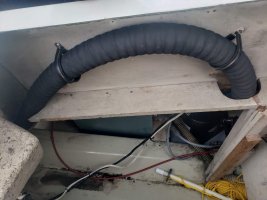
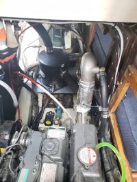
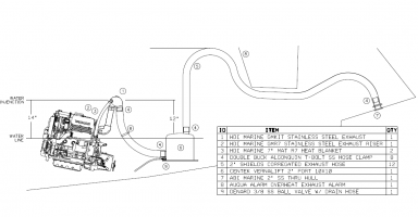
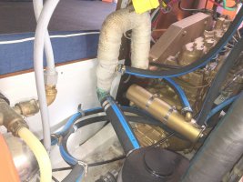
Segue has a new exhaust system! Everything from the exhaust manifold to the back of the boat has been replaced. Even the plywood the muffler sits on was replaced. I went with Shield corrugated exhaust hose to help with the bends below the cockpit sole, on to the thru hull, and to the outlet of the muffler. I also added a 7” riser from HDI marine before the mixing elbow to get a full 12” drop from the water injection point to the top of the muffler. An added bonus was getting 14” from the injection point to the water line which removes the need for a vented loop. The riser caused a little issue with the water injection hose since the port on the back of the heat exchanger is a little larger than ¾ but the nipple on the mixing elbow is 5/8. Yanmar sells a special hose for this, but it’s too short to account for the riser. I tried to heat some 5/8 heater hose to fit around the ¾” port, but it didn’t go as well as I hoped. In the end, I went with a barbed splice to add a 6” piece of 5/8” hose to the original Yanmar hose.

I also added a valve to the front of the muffler to make draining easier as the drain bolt that comes with the muffler is in an awkward spot. I used the old muffler to test drilling and tapping NPT threads. This saved me from buying a third muffler as I realized the wall wasn’t thick enough and I needed to add a piece of G10 to provide additional material for the treads to bite.

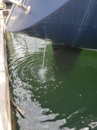
Enlarging the thru hull turned to be much easier than I had anticipated. I was worried about blowing out the fiberglass, gelcoat, or Awlgrip paint with the hole saw. However, the backing plate I epoxied to the hull provided a good guide for the hole saw and the old thru hull flange kept the outside intact. I used butyl tape to temporarily seal the thru hull while its in the water. When I have the boat on the hard and have better access, I’ll reseal it with something else.

The only thing left to do is add the exhaust temp sensor which will give me some piece of mind that I won’t burn up all this work. 20200509_111842.jpg20200517_140509.jpg20200517_140528.jpg20200517_152715.jpg20200517_153831.jpg

 

Kenneth K

1985 32-3, Puget Sound
Blogs Author
Nice install--good job. I like the new thru-hull. I'd much prefer that to the plastic stuff I have.
 

Nick J

Contributing Partner
Moderator
Blogs Author
Thanks ken. removing all plastic stuff was my initial thought as well. However, I have to say the one I removed looked good as new and had zero corrosion. I can't say the same for the bronze elbow though.
 

Kenneth K

1985 32-3, Puget Sound
Blogs Author
Hey, I'd be interested to hear if the engine runs any differently with the 2" exhaust hose. I had heard that a 2" hose would reduce back-pressure resulting in more power and /or less vibrations, but I stuck with the 1 5/8" hose because the back-half of my exhaust system was all in good shape.
 

Nick J

Contributing Partner
Moderator
Blogs Author
I'd be interested too. Unfortunately, I'm embaresed to say, I've only run the boat twice. The first time was for the survey where we found the prop encrusted with barnacles and the alternator belt was loose. Both issues kept us from pushing it much above 1200 rpm for most of the trip. The second time was delivering it from Port Hadlock to Everett and the sailing was too good to put the motor through any kind of test. Had I known I was going to overhaul the exhaust system, I would have tested it a little more for a good point of comparison.

I still don't know if going to two inch is necessary given the restriction in the exhaust elbow, the fact that 2“ is "required" by yanmar for their 3ym15, 3ym20, and 3ym30 (leading me to believe it isn't specifically sized to my 3ym20), and the lift from the muffler to the top of the loop seems like so much more restriction to flow that the difference between 2“ and 1 5/8" would be negligible by comparison.

I had problems with every component in the system which led me to a full replacement. The only extra bit for going 2" was having to enlarge the thruhull. Seemed like it was worth it for me. If the thruhull and existing 1 5/8 was good, I probably would have left it.

If your looking for an excuse to make the jump, I did notice some of the hose that looked fine on the outside had spots where the inner lining of the house was damaged and separating from the outer section. Of course the manufacturers say they are only good for 10 years and mine were 14 years old. I'm hoping the exhaust temp sensor will reduce damage like this in the new system.
 

Christian Williams

E381 - Los Angeles
Senior Moderator
Blogs Author
An added bonus was getting 14” from the injection point to the water line which removes the need for a vented loop.

Can you tell us the injection-point-to-waterline guideline distance for eliminating a vented loop?
 

Kenneth K

1985 32-3, Puget Sound
Blogs Author
.... and the lift from the muffler to the top of the loop seems like so much more restriction to flow that the difference between 2“ and 1 5/8" would be negligible by comparison.

That's always been my hunch--that that "lift" is where the real back pressure is created. Yet, people still seem to claim an improvement from enlarging to a 2" hose, which I why I asked if you've noticed a difference.

And a final point. That 1 1/4" Marleon ball valve you pulled from the old exhaust elbow may have been a choke point as well. The opening inside those valves is only 15/16" ID. I've been thinking of pulling mine for that reason.

Congrats on the new boat.
 

Nick J

Contributing Partner
Moderator
Blogs Author
Christian,

Short answer - minimum 12" with 16" or more being ideal.

My reasoning:
I found answers all over the internet ranging from above the water line to 24” minimum and even the always popular “as high as possible”. I ultimately used the document Ken referenced as it made the most sense to me. From what I understand the siphon break is only needed if your injection point is below the water line. This protects you from water siphoning past the impeller, filling up your muffler, and back flowing into your engine (and probably through the valves to ultimately flood your boat). A siphon can’t form if the injection point is above the waterline which mine was by 8” with the standard mixing elbow.

Of course, there’s always safety factors to account for additional pressure due to boat speed, change in water level due to weight or healing, and waves which the standards try to account for. The most common standard I found was a minimum of 12” above static waterline with 16” or more ideal. If I stuck with the standard mixing elbow, I would have added a siphon break (probably where you have yours) to get the 12".

The document also states a minimum of a 12” drop from the injection point to the top of the muffler. This standard seems important to me as I can see instances where the engine won’t start and I could inadvertently fill the exhaust system and ultimately the engine. I tried to mitigate this risk, by raising the injection point to 12” above the muffler and adding an easily accessible drain valve to the front of the muffler. This had the added benefit of getting the injection point 14” above the water line. I measured the waterline by pulling the raw water foot pump inlet off the thru hull and temporarily installing a clear tube then opening the valve and marking in the engine compartment. It ended up being about the height of the quarter birth.
 

Christian Williams

E381 - Los Angeles
Senior Moderator
Blogs Author
Very good, thanks.

On my E381, the heat exchanger sits low--somewhat near the waterline. Also, the injection point on the exhaust elbow is quite low, with much less than the minimums you cite.

That must be why a high vented loop was installed on my model.

.2 diesel hoses complete wide.jpg
 

Nick J

Contributing Partner
Moderator
Blogs Author
Once again, pictures clear it all up. That's definitely at or below the waterline. It looks like the water injection point on Universals is kind of a custom setup. No chance of have a mixing elbow fail and sending raw water into your exhaust manifold.

I'm also envious of the engine access on your boat. the quarter birth plywood and engine housing on my 35-3 don't seem to be as easily removable as yours. I'm stuck doing everything through small hatches.
 
Top