• Untitled Document

    Join us on April 26th, 7pm EST

    for the CBEC Virtual Meeting

    All EYO members and followers are welcome to join the fun and get to know the guest speaker!

    See the link below for login credentials and join us!

    April Meeting Info

    (dismiss this notice by hitting 'X', upper right)

Solar 'generator' backup battery systems

Filkee

Sustaining Member
2×160 is a lot of Watts. Nice. Have Any pictures of where you put the controller? I like the display on the Renogy controllers.

Also, does the Bluetooth module add much when you can just read it off the display?
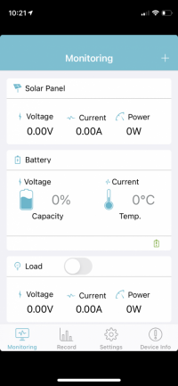
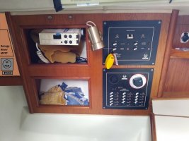
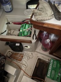
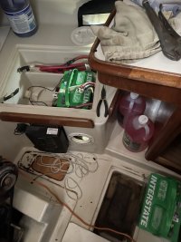
Actual production is always a fraction of the nameplate so I aimed high. On the panels. Because of the ventilation clearances required, I wound up putting the controller in an awkward spot that made the Bluetooth pretty helpful. Hard to describe but if you’re sitting at the chart table, reach down with your right hand and knock on fiberglass. That’s the spot. Nice short run to the battery box but not too long a run from the panels. Oh, wait found a picture D3DECF23-331D-4450-9C85-C85513CF895F.jpeg
 

Filkee

Sustaining Member
And here’s a screen shot of the app all zeroes because I’m at home and so are the panels 421A7F03-D82B-4806-8C6B-641144360B7A.png
 

Kenneth K

1985 32-3, Puget Sound
Blogs Author
Oh, wait found a picture
Yeah, nice, thanks. Handy place for a second round inspection port, too--I don't have one there. I'm considering adding a panel aft of the current panels. Something like this:

Solar.jpg

I could probably make do with a Renogy 20A or Victron 15A. Would be nice if the Renogy could fit there with the ability to read the display.

Helps to see what others have done. Thanks.
 

p.gazibara

Member III
Food for thought. It might cost a bit more, but I am unbelievably happy with our setup.

Our Midnite Kid solar charge controller has gotten a salt water enima. The same enima that killed our KVH sailing instruments when we were pooped by a wave going south down the WA coast.

The Kid never skipped a beat. Apparently the US military uses them as well and one was hit by a mortar shell and still continued to work...

They are made in Arlington, WA and I have visited their facility. Top notched folks making top notched products.

It’s capable of 30 amps, and our 700w of solar has kept it maxed out for hours without overheating or causing any issue with the unit.

Our panels were also US made, but unfortunately SolarWorld was put out of business due to a some shitty tariff laws. One of them blew off our deck and sat 4 meters below water for 2 days before I convinced a friend to get his scuba tank out and go find it. It still works flawlessly...

Yeah, you can find cheaper options, but I don’t like buying things twice anymore.

-p
 

nquigley

Sustaining Member
Neil,

Where'd you get that great looking brass lamp in your first picture? Is it LED? I assume it's a straight-forward swap-out. As you probably know, the original Ericson ones are kind of flimsy. Several of mine will no longer hold the screws that screw into the sides.
I got 3 of those lamps: one at the nav station and two for the V-berth. I think I got them from Fisheries Supply, but their site is down right now so I can't check.
Yes - LED.
Yes - direct replacement for the rather poor quality OEM lamps. But the wires are rather small - I tried to solder them (I'm not good at that), but went with small crimped connectors in the end - it was a bit fiddly, but well worth doing. I had trouble finding LED bulbs for the OEM lamps, which is what prompted me to make the swap.
The base of the new ones was very slightly (~1/8") wider than the OEM ones, so I had to slightly pinch the base to make it fit between the panel and the cubby hole's frame by the nav station, but the screw holes matched.
 
Last edited:

nquigley

Sustaining Member
Yeah, nice, thanks. Handy place for a second round inspection port, too--I don't have one there. I'm considering adding a panel aft of the current panels. Something like this:

View attachment 37678

I could probably make do with a Renogy 20A or Victron 15A. Would be nice if the Renogy could fit there with the ability to read the display.

Helps to see what others have done. Thanks.
My two 100W panels are Renogy - coming through a Victron 75|15 controller. Seems to work fine, and it's handy getting all the realtime and historical charging data via bluetooth on my phone (same for my Victron 712 battery monitor).
 

Filkee

Sustaining Member
Yeah, nice, thanks. Handy place for a second round inspection port, too--I don't have one there. I'm considering adding a panel aft of the current panels. Something like this:

View attachment 37678

I could probably make do with a Renogy 20A or Victron 15A. Would be nice if the Renogy could fit there with the ability to read the display.

Helps to see what others have done. Thanks.
I found LEDs for the OEM lamps here: https://store.marinebeam.com/

got the ones where the can toggle between red and wam white fir the Mac station.
 

nquigley

Sustaining Member
I found LEDs for the OEM lamps here: https://store.marinebeam.com/

got the ones where the can toggle between red and wam white fir the Mac station.
I mounted and LED Red/White/off dome lamp under the companionway in place of the dome OEM white/off one. I also have a red/white/off light on a flexible arm at the nav station - it replaced that odd black OEM one with the convex lens (which had stopped working). Having all-LED lights on board is very satisfying! (the only one I haven't replaced with LED yet is the white all-around one at the masthead - a new replacement lamp is in the cabin waiting for the lazy owner to go up there and install it.)
 

Filkee

Sustaining Member
I sliced that wonky broken light off and turned it into an iPhone charger. Hoping my son will be grateful enough to climb up someday and replace the anchor light. :)
 

Kenneth K

1985 32-3, Puget Sound
Blogs Author
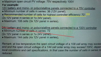
Can someone help me decipher this (from the Victron MPPT manual):

20210316_233033_2.jpg

I currently have two 50W monocrystalline panels. How do I know how many "cells" I have? I was assuming that hooking them up in parallel, to a single controller would be best (if one panel is in the sun, the other panel will pretty much be shaded). Not sure how to reconcile the above paragraph with my plans. Long term plan may be to add another 150W panel (flexible) to the dodger top. For 250W, I'm considering a 20A controller.
 
Last edited:

Filkee

Sustaining Member
Looks like the whole “example” is on a completely different scale. You can count the number of rough squares on your panels if it makes you feel better. You probably have a couple of dozen on the 50s. Your instincts are right with the two panels parallel. There will be boom shadow and you will at some point find yourself obsessively adjusting your traveler to keep them both in the clear.
 

nquigley

Sustaining Member
Can someone help me decipher this (from the Victron MPPT manual):

View attachment 37780

I currently have two 50W monocrystalline panels. How do I know how many "cells" I have? I was assuming that hooking them up in parallel, to a single controller would be best (if one panel is in the sun, the other panel will pretty much be shaded). Not sure how to reconcile the above paragraph with my plans. Long term plan may be to add another 150W panel (flexible) to the dodger top. For 250W, I'm considering a 20A controller.
This link gives panel size vs # of cells: 60-cell panel (~270-300W) is ~5 x 3 ft
I think my 100W monocrystalline Renogy panels are 33 cells each. Both go into one Victron 75|15 MPPT controller (wired in parallel for the same reason as you're thinking about)
 

windblown

Member III
Actual production is always a fraction of the nameplate so I aimed high. On the panels. Because of the ventilation clearances required, I wound up putting the controller in an awkward spot that made the Bluetooth pretty helpful. Hard to describe but if you’re sitting at the chart table, reach down with your right hand and knock on fiberglass. That’s the spot. Nice short run to the battery box but not too long a run from the panels. Oh, wait found a picture View attachment 37676
Filkee,
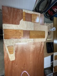
this is off topic, but I don’t know how to capture your image to start a new thread, perhaps a moderator can help? This picture shows the TAFG and structure under this section of the sole where I have a water incursion problem I haven’t been able to trace. After a sail with light to moderate seas, there is always water under this area of the sole. (If I step on the most aft point, I can get bubbles or water over the edge; the varnish is delaminating; sole is discolored, and there is a seam showing a previous owner had cut out and replaced this section.). The water never makes it to the bilge, leading me to think that perhaps there’s water trapped in some TAFG pocket astern that moves when we’re heeled to starboard or bouncing through chop. Any ideas from what you’ve seen around there?
 
Last edited:

Christian Williams

E381 - Los Angeles
Senior Moderator
Blogs Author
Here's the photo again, as requested.

For what it's worth, many tab openings aren't connected to the bilge. If they collect water, it's from seepage under the sole, and they have no way to drain. It's an annoying issue for boats with glued-down soles which permanently cover such pockets.

And yeah, I concluded that bilge water gets forced into weird places in the TAFG heavy weather, and slowly drains later to wherever it can.

filk.jpeg
 

Filkee

Sustaining Member
Here's the photo again, as requested.

For what it's worth, many tab openings aren't connected to the bilge. If they collect water, it's from seepage under the sole, and they have no way to drain. It's an annoying issue for boats with glued-down soles which permanently cover such pockets.

And yeah, I concluded that bilge water gets forced into weird places in the TAFG heavy weather, and slowly drains later to wherever it can.
I was surprised at how much oil had accumulated in the shallow one.
 

Kenneth K

1985 32-3, Puget Sound
Blogs Author
Ok, it's pretty easy to count the cells, even from the pictures on Amazon. The Renogy 100W and 50W panels both appear to have 3 columns of 11 cells each for 33 total. The height of the cells is 50% smaller on the 50W panels, so the cell count is the same though the panel is 50% smaller.

That answers my first question--it wouldn't necessarily be any better to run 100W panels (vs the 50s I have) with a Victron 75/15 controller. But it conflicts with this:

"A solar power panel is made of photovoltaic cells arranged in a configuration that can contain 32, 36, 48, 60, 72 and 96 cells. A solar panel comprising 32 cells typically can produce 14.72 volts output (each cell producing about 0.46 volt of electricity). These cells are arranged in a frame that is either rectangular or square. The size and weight of solar power panels increase as the number of cells increase." Link
Apparently the Victron (maybe all MPPT) controllers like higher voltages. Sounds to me like they are saying that running two 12V panels in series (for 24V) is optimal (ignoring the shading issues). It's the 36 cell minimum that doesn't make sense to me; everybody runs these Renogy panels with MPPTs.

I didn't see any similar remarks in the Renogy Rover MPPT controller manual.
 

Kenneth K

1985 32-3, Puget Sound
Blogs Author
Deborah,

I used to have a squishy sole in that same area. The sole was so easy to lift up in that area that it tricked me into removing the whole section. Unfortunately, the further I got away from that area, the less the adhesive had loosened, and the harder it became to remove the sole.

When I finally removed it, it looked like this underneath:
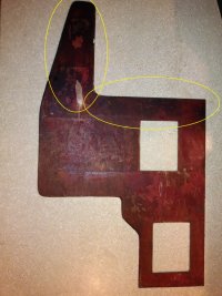
C (4).jpg

I saw no way for water to come in from below (from the TAFG) in this area. That little plywood cover over the TAFG-well (shown in Filkee's picture) was sealed in so firmly with heavy-duty caulk that I had to destroy it to remove it.

My theory is that any water from the galley area flows along the seam where the sole and TAFG meet, looking for a place to pool where the sole is not well-adhered. The darkened areas in my photo show the places that were exposed to water, even though I only noticed under that aft-most tab, where I could see the water squeezing out.

About the only other thing that "drains" into this area is, possibly, fluids from the engine.
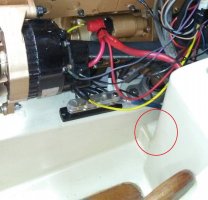
20170906_150109.jpg

I've had water running down that little track to port of the engine after changing the heat exchanger zinc. Also, diesel spills after changing fuel filters. I believe this is why my sole was so loose in this area--the wood had a strong diesel smell when I removed it. That's probably what softened up the glue.
 
Top