TAFG layout for a 1987 E-32

RHenegar

Member I
I am trying to find a drawing, picture or anything that will show me the layout of the TAFG on my 1987 E32. I am trying to route a drain line for the AC unit under the V berth to the shower sump to keep the AC drain water out of the bilge. I am looking for a path. My cabin sole is glued down ( really dumb idea) so I can't pull it up and look. The picture in the brochure on line gives me some idea, but is not detailed enough. Anyone have any ideas on where to find it? Or does anyone have any experience pulling up the glued down cabin sole so I can look myself?
 
Last edited:

Christian Williams

E381 - Los Angeles
Senior Moderator
Blogs Author
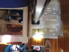
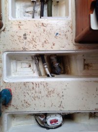
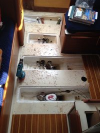
Maybe these photos will help (from 1985 32-3).

The glued down sole is permanent, so you'll have to work through the access lids.

Any fore and aft run would have to go through the limber holes.

1-IMG_2854.JPG1-Thelonious bilge B.jpg1-Thelonious bilge A.jpg
 
Last edited:

Bolo

Contributing Partner
Mermaid Condensator

FYI: I have a Webasto AC/heat pump in my 32 under the v-birth and installed a Mermaid Condensator which works well. Collects the water and sends it out with the water that runs through the AC. Here is a link for it but I I didn't buy it from this distributor. I can't recall where I bought it actually because I installed it long ago. Mermaid has a new improved and more expensive one now.

http://www.marinewholesales.com/en/product.php?id=477
 

MMLOGAN

Member III
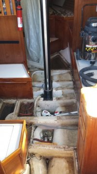
84 E-35 peak under the sole

Here's what was under ours:20131103_131446.jpg
 

Attachments

  • 20131103_131440.jpg
    20131103_131440.jpg
    40.3 KB · Views: 201

RHenegar

Member I
Thanks all

These photos are great, and they explain why I couldn't find a path from the v berth back to the shower sump. I am not ready to tackle the cabin sole yet so I may just have to let it continue to drain into the bilge. I have looked at the system that extracts the water into the cooling water outflow, but I have concerns about backflow. Any issues there?
 

MMLOGAN

Member III
Previous post is missing

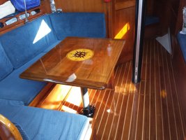
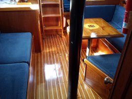
Here's the short version. We redid the sole during the winter of 13. Cleaned every surface. Corrected all of the limber holes that retained water in a chamber by drilling new holes or raising low spots with gelcoat. Machined teak and maple for a semi tongue and groove install. Screwed down marine ply that had been coated on every surface with epoxy to the TAFG. Bonded the teak and maple to the ply with epoxy. We used Bona Floor Poly - oil modified. 7 coats. I have re-coated once with the same product and still really like it. Here's a couple of finished shots:
20140607_164905.jpg20140607_164924.jpg
The last shot shows the final product bonded together and our version of tongue and groove.
 

Attachments

  • new sole piece.jpg
    new sole piece.jpg
    22.8 KB · Views: 154
Last edited:

RHenegar

Member I
@ Granpa Steve

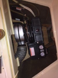
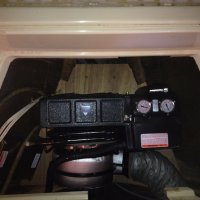
Yes I do have a water tank in the bow. When I purchased the boat it had an AC unit mounted in the storage tub under the V Berth. The unit was old and noisy and vibrated. Being mounted in that tub which is part of the V berth, every time the compressor kicked in it turned my V berth into a "magic fingers" bed. After doing some investigating I figured there was a ton of space below and around that tub, so I cut the tub out and built in a mounting platform for the new 16k AC unit that attaches to the stringers built into the hull and to forward bulkhead for the V berth. The puts the weight of the AC unit lower in the hull which is a good thing, and the AC is no longer directly attached to the V berth so no vibration. I cut the tub about 1/3 the way down from the top so I was able to install a false bottom to the storage area above the top of the new AC. I store bedding and towels in that space which acts as sound insulation. It wasn't that hard.

IMG_0411.JPG IMG_0412.jpg
 
Top