VIDEO: E35-II Hull Flexing at Groco Seacocks

ignacio

Member III
Blogs Author
KS_Flex_Groco.jpg

https://youtu.be/IorGAu0yhdk

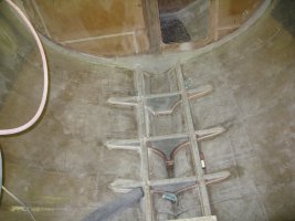
I took this video in 3-5 foot seas, winds to 15 knots on a dead run, approximately 300 miles east of Kauai. The hull flex shown here is located directly beneath the forward area of the cockpit, just under the bridge deck. Note that the through-hull, flange, valve, and T-fittings are all new Groco parts installed in April 2016, or 2 months before this video was taken. The flange is through-bolted to the hull at three points, and the backing plate is made from a 5.5" round 3/8" thick G-10 sheet. The bronze bolt heads on the outside are countersunk and sealed in epoxy. No leaks were noted here during the transit from LA to Kauai, or about 2,200 miles. Biggest seas on this transit were 10-15' for 48 hours during the first leg of this transit (prior to the video being taken) The assembly replaces the original installed by Ericson, which was just a through-hull screwed directly into a valve, supported by a plywood backing plate with a lock nut, along with the two additional T-fittings: one for the galley sink, the other for the starboard scupper in the footwell behind the wheel. After observing this flex, this is one upgrade I'm glad to have made (both sides).

There's theory, and then there's the cold reality of watching this in a seaway. Watching this, I knew that FRP and that our hulls are meant to flex, and that all boats have some degree of flex. Take for example, this video of this steel container ship: https://www.youtube.com/watch?v=PmlTk_3NN_g. I also knew that the hull-to-deck joint is completely glassed together on the E35-II, further strengthening the whole boat. During the transit, I made it an almost daily routine to inspect bulkhead tabbing, the hull-to-deck joint where practical to inspect, chain plate attachment points on bulkheads, the ability to open and close locker and head doors, evidence of gel coat crazing in the liners and floor pan, and anything else that would indicate that attention would be needed. I also inspected the rudder tube, gland, and post, the quadrant and steering cables....all sorts of things. I saw nothing out of the ordinary...no cracking of FRP, no crazing gel coat, no bulkhead separation.

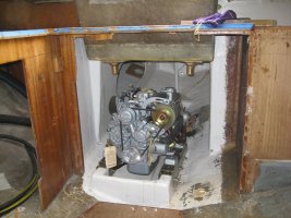
One additional note: The engine cover on my E35-II is located under the dinette...great access to the engine. With the hull flex shown in the video, the wooden engine cover produced enormous amounts of noise as it rubbed against the FRP floor pan, which is NOT bonded to the hull on these early boats...the floor pan just sits on top of plywood stringers below it that are bonded to the hull. The most interesting thing about this wasn't the noise necessarily. It was that, when I removed the engine cover, it was nearly complete silence in the cabin. You'd hear the occasional crackle of wooden furniture or bulkheads here and there, but the silence was in sharp contrast to the noise produced by the engine cover. I took all this evidence (especially the silence in the cabin) to mean that the boat was operating well within the design limits in the sea state I was in, and that the hull flex was simply also part of the design. Separate and apart from that, however, she somehow seems "more loose" after that voyage...not sure if it's always been there and I'm just now noticing it because of the amount of time I just spent in my boat, or if it's something new from having crossed 2,200 miles of open ocean.

Not necessarily a question here, but thought I'd post this for observations/comment.


Last edited:

Phil MacFarlane

Member III
For what it's worth, I once wanted to remove the floor pan from my E-35 MkII but consulted with Mr King first. I told him that my floor pan moved around inside the hull and he told me that was not right. The floor pan was an integral part of the boat and should be bonded to the hull everywhere possible. So I left it and bonded it to the hull everywhere possible.

Still got lost of hull flex on my 6 crossings. Don't think it's much to worry about.

Congrats on the sail. Now all you have to do is the hard part :)
 

ignacio

Member III
Blogs Author
Still got lost of hull flex on my 6 crossings. Don't think it's much to worry about.

Congrats on the sail. Now all you have to do is the hard part :)

Worried? Who's worried? :0

Up on deck, she consistently felt strong in the swells...didn't feel the flexing at all. And since my daily review revealed nothing, I concluded what we already know: That these Ericsons were designed and (largely) built well. Your six crossings further confirms this for me.

I still think that the area under the cockpit isn't well supported, at least on my boat. The fore/aft bulkhead in the starboard cockpit lazarette is only screwed in at the top on my boat. Same for the fore/aft bulkhead in the quarter berth, and that one has the distinction of not being secured to anything at all at the top, and only screwed-in everywhere else. I'm considering glassing those in before I leave for SF, but leaving an access panel on each to reach the quadrant and fuel tank fittings.
 

Zbingham

Member I
For what it's worth, I once wanted to remove the floor pan from my E-35 MkII but consulted with Mr King first. I told him that my floor pan moved around inside the hull and he told me that was not right. The floor pan was an integral part of the boat and should be bonded to the hull everywhere possible. So I left it and bonded it to the hull everywhere possible.

Still got lost of hull flex on my 6 crossings. Don't think it's much to worry about.

Congrats on the sail. Now all you have to do is the hard part :)

I have my E35 mkII torn apart and I am looking for ways to improve on the original design and reinforce it as I put it back together. I was considering removing the floor pan and glassing-in stringers and floors and then installing a plywood sole on top. It seems like a typical stringer and floor construction would be a lot more solid than a molded fiberglass pan, and that the reason they put the molded pan was to save on construction costs.

In another attempt to to add more hull rigidity, I am considering glassing-in some plywood where the wood ceiling attaches to the inner sides of the hull. The plywood that was originally installed was just epoxied on. By actually glassing it completely in I think it would add quite a lot more strength. I was also planning to fully tab-in the bulkheads Ingacio is talking about under the cockpit.

Do you guys think it is possible to add too much strength or rigidity to the hull? Is there a possibility that strengthening one area it may cause more stress on a different area?

Great job on the preparations to your boat and also on the crossing Ignacio! Keep those videos coming!
 
Last edited:

Phil MacFarlane

Member III
I just watched your videos and I'm really happy to see there is someone more nuts than me.

You are probably right about it being cheaper to put in the pan rather than stringers like the olden days but... these hulls probably don't need that much support. I added stiffeners in the bow area where the sides are so flat but I never felt I needed to stiffen anywhere else on the hull. Although I did re-tab everything and replaced seven bulkheads so far. You can get cracks in the gelcoat outside if you do it wrong but you probably know that.

The original plywood on the sides is only there so they could screw the wood ceiling to it. It's not structural.

You have gone so far you might as well do whatever you want at this point.

If you do the face book I'm on there with a few thousand pictures of projects on my boat, look me up if you want.

Best of luck!

Phil
 

PDX

Member III
I've never seen an E-35-2 torn down, so I can't speak with any authority on how the hull construction compares to an E-30-1. But I've never regretted the home brew TFG job on my boat, or any of the other stiffening measures which were considerable. I really don't see any downside so long as you go heavier on the cloth than on the mat (which is more brittle and can create hardspots). Also, I suggest using medium density foam, anywhere you want to develop stringers or hat section support, in lieu of plywood.

BTW, on my boat the plywood backer underneath the side deck was purely cosmetic, hiding wiring and the edge of the headliner. Most E-35-2s had headliners. You can certainly stiffen the area where the cabintop meets the side deck with a hat section and tabbing (I did) but you'll have to cut through the headliner (I removed mine completely).
 

toddster

Curator of Broken Parts
Blogs Author
I'm not too surprised by the flexing. But your post does bring up an interesting idea. I've been wanting to add a scupper to the forward end of my cockpit, which presents certain plumbing challenges. But I hadn't previously considered tee-ing it in to the galley sink drain. Hmm...
 

ignacio

Member III
Blogs Author
I'm not too surprised by the flexing. But your post does bring up an interesting idea. I've been wanting to add a scupper to the forward end of my cockpit, which presents certain plumbing challenges. But I hadn't previously considered tee-ing it in to the galley sink drain. Hmm...

That starboard side through hull has two T's: one for the starboard side cockpit scupper in the foot well behind the pedestal, and the other for the galley sink. The top hose is the drain for the foot well in front of the pedestal. I think this was standard on the 35-2, don't know if I'm a fan of this arrangement. On top of being a big, strong lever arm on the hull, the galley sink frequently gurgles, burps, and floods the galley sink in lively seas and when heeled on port tack. I guess it's probably better than another through hull (but not totally convinced).

Also, after seeing the flex, I'm glad I installed that through-bolted flange which adds strength. my old dezincified valve/through hull arrangement was so far gone I'd hate to think of how it would have performed on this crossing.
 
Last edited:

ignacio

Member III
Blogs Author
I just watched your videos and I'm really happy to see there is someone more nuts than me.

I don't know. I figured that distinction usually went to the guy who could modify his boat the most and get the most ocean miles on said boat. I don't know who that would be though. Oh wait.
 

PDX

Member III
Any pics/detail of what you did?


Medium density foam pieces were used for stringers and cross supports. Then glued down w/epoxy and covered with biaxial cloth and vinylester (way easier to use than epoxy, particularly with a big job). The forward part of the frame dead ends into a compression post step that I had built extending from the main bulkhead through the head area. The aft part of the frame dead ends into an engine mount base I had fabricated out of medium density foam covered with cloth and resin (same principle as the TAFG frame).
Adding all these items together (compression post step, TAFG, engine base) the two halves of the hull are now stabilized athwartships from head through the engine compartment.

One of the things I had discovered about two piece Ericson hulls (mine at least) is there was almost no interior stiffening athwartships. The forward bulkheads were only partial bulkheads, open in the middle. The two hull halves were held in place by a strip of 24 oz roving, about 10 inches wide, extending the length of the boat, but other than that the two hull halves were nearly structurally independent. And there was no such strip on the outside of the hull--the gap between the two halves was filled in with some kind of putty. That was it. Anyway, I also replaced the existing forward bulkheads with complete bulkheads, MDO plywood, with step through holes cut in (ring bulkheads actually).


attachment.php
attachment.php
attachment.php
attachment.php
attachment.php
 

Attachments

  • IMG_7873.jpg
    IMG_7873.jpg
    89.1 KB · Views: 78
  • IMG_7635.jpg
    IMG_7635.jpg
    120.9 KB · Views: 73
  • IMG_5219.jpg
    IMG_5219.jpg
    86.1 KB · Views: 88
  • IMG_5221.jpg
    IMG_5221.jpg
    95.2 KB · Views: 85
  • IMG_2493.jpg
    IMG_2493.jpg
    107.3 KB · Views: 65
Top