• Untitled Document

    The 2024-2025 Fund Raising Season has Opened!

    EricsonYachts.org has opened the season for raising funds to support the expenses of the site. If you would like to participate, please see the link below for additional information.

    Thanks so much for your continued support of EricsonYachts.org!

    2024-2025 Fund Raising Info

HELP!- Wiring Issues

kapnkd

kapnkd
So what's a better alternative to the displacement-type 'tap' connectors? Say I want to wire a new cabin light into the existing factory wiring harness, is there a better option?
Our biggest problem when installing the new cabin lights to the old inside the liner wires was having enough old lead wire left to actually connect to. We weren’t fussy and simply used what worked best for good solid connections.
 

bigd14

Contributing Partner
Blogs Author
So what's a better alternative to the displacement-type 'tap' connectors? Say I want to wire a new cabin light into the existing factory wiring harness, is there a better option?
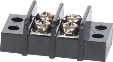
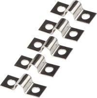
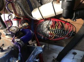
Terminal blocks and ring connectors. You can get jumpers for them if two ring terminals won't fit. In the third photo the last wires to the right are doubled onto a terminal block.

2402.jpg


9216.jpg
863B4B99-A31E-45C4-9668-2C077742F4B4.jpeg

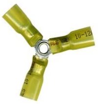
EDIT, you can also get three way connectors. And make sure if the cabin light wires are smaller than the wire run that the fuse or breaker is sized appropriately for the smaller wires.
3 Way.jpg
 
Last edited:

Christian Williams

E381 - Los Angeles
Senior Moderator
Blogs Author
Those three-way spiders never work for me because the wires tend to be different sizes, and I don't have the right piece, and because they look odd--especially the cheaper ones.

I admit that sometimes, in the case of say connecting a compass light to the running lights, I just scraped the insulation off the existing wire run, then wrapped the smaller compass wires around the exposed copper and taped it. Not approved by NASA but "close enough for jazz."

Not a heretic about doing it right, as when rebuilding a panel. I just think whatever works is often fine for noncritical components in our inaccessible spaces. (Try getting a heat gun under the headliner to shrink a buried connector.)

To dig the grave deeper, I have wire nuts aboard, the very idea of which makes some people crazy. For temporary connections and testing circuits they're really handy, and even if you leave them on for a week nothing explodes.
 

Nick J

Contributing Partner
Moderator
Blogs Author
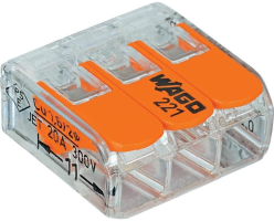
Wago nuts work pretty well and are less susceptible to vibration than wire nuts. I've started using them in my house and have a few on the boat. keep them in dry areas and they should be good. They're great for circuits your tend to rework often like lighting.
1655478894341.png
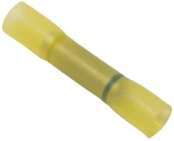
For connections in less dry areas like bilge pump wiring I use heat shrink step down butt splice terminals:
1655479053642.png
Just put two connectors in the 10-12 side, crimp, and test before applying heat. So far it's worked well for me.
 

Tin Kicker

Sustaining Member
Moderator
So what's a better alternative to those displacement-type 'tap' connectors? Say I want to wire a new cabin light into the existing factory wiring harness, is there a better option?
As others said, we are not NASA or building airplanes here. In those situations I cut the original wire and use a plain butt splice, just a size larger if need be so two wires can go in one end. Run the new wire into one side along with the original (twisted together), then for the other side of the butt fold the end of the stripped wire back on itself to fill the connector. It accomplishes the same purpose as the 3-way shown above.

If the original wire is short, follow it to the nearest end and replace that section, adding a few inches in case something else needs to be done in the future.

And again, I tend to fill the ends of the butt splice with liquid rubber/tape. It both sells out moisture and minimizes creating a fatigue or flex point.
 

shard7

1974 E27 'Bluey'
As others said, we are not NASA or building airplanes here. In those situations I cut the original wire and use a plain butt splice, just a size larger if need be so two wires can go in one end. Run the new wire into one side along with the original (twisted together), then for the other side of the butt fold the end of the stripped wire back on itself to fill the connector. It accomplishes the same purpose as the 3-way shown above.

If the original wire is short, follow it to the nearest end and replace that section, adding a few inches in case something else needs to be done in the future.

And again, I tend to fill the ends of the butt splice with liquid rubber/tape. It both sells out moisture and minimizes creating a fatigue or flex point.
Thanks, those are great suggestions! I like the idea of the butt splice with two wires on one side. It kinda pains me to cut into the middle of a continuous wire run and insert a butt splice there, but perhaps that's okay if the butt splice is installed and sealed properly.
 

Prairie Schooner

Jeff & Donna, E35-3 purchased 7/21
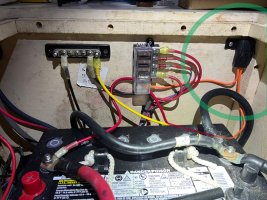
battery wiring 2024_4 a.jpg

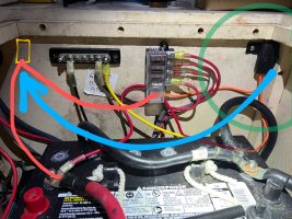
What is this Black Plug (circled in green)? It is fed from the positive terminal of the battery. I pasted in some color to show what is hidden by the battery.

This wiring is from when the electronics folks wired our new chartplotter, instrument displays, VHF, and AIS. They didn't label anything, and I need to follow up with them when they install our radar.* But I am wiring some things now and am trying to figure out the rest.

*Overall we're pleased with their work, but I'm irked they didn't label things or give us a schematic.
 

shard7

1974 E27 'Bluey'
@Loren Beach @Kenneth K
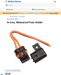
Thanks guys. Why would there be a fuse before a fuse box?
The fuses in that block protect each of the circuits that it feeds, and typically have a lower rating. That inline fuse protects the wire from the battery to the fuse block, and it carries all of the current so it needs to be thicker and have a higher rated fuse on it. It's similar to the main breaker vs branch circuit breakers in your home electrical system.
 

Prairie Schooner

Jeff & Donna, E35-3 purchased 7/21
Thanks @shard7 !! - I was writing this as just your post came in. You said it much more succinctly.

A friend with a long history in senior management has a couple aphorisms for saying the same thing:
"Ready, Fire, Aim."
"Why act when you can overreact?"
I might add, "Why read The Book when you can write a question in a post?"

So, going to my copy of Calder's book this morning, 4th edition, page 237, (italics from the text):
". . . the purpose of the overcurrent device, which is to prevent the wiring in the circuit from melting down in the event of a short circuit. Since the most heat in any circuit will be developed by the section of wiring with the highest resistance (the smallest wire), for any given circuit, an overcurrent device is sized to protect the smallest wire in the circuit.

For example, if a GPS, which draws minimal current, is hooked into a circuit wired with 12-gauge (3 mm2) cable, the overcurrent device should be rated to protect the wire from melting down, not the GPS. Something on the order of a 20 amp fuse or breaker will do fine. Separate protection (generally a fuse, probably as low as 1 amp) will be needed for the GPS or any other equipment on the circuit.

Having said this, if a circuit breaker in a distribution panel protects a circuit to a single load, and the protection required by the load is less than that required by the cables, the breaker can always be sized to protect the load, down to about S amps, which is typically the smallest breaker available. If, on the other hand, the same approach is used for a breaker that protects several circuits, the sizing is a little more complex. Two factors must be considered: (1) the total load of all the electrical equipment to be served by the breaker, and (2) the current-carrying capability (ampacity) of the smallest wire being protected (Figure 4-77A). The breaker must be sized according to the lower of the total load or current-carrying capability of the smallest conductor."
 

Kenneth K

1985 32-3, Puget Sound
Blogs Author
That inline fuse protects the wire from the battery to the fuse block, and it carries all of the current so it needs to be thicker and have a higher rated fuse on it.
Yeah, but it's in the wrong space. The 9-12 inches of wire between the battery and the inline fuse is unprotected and unsecured (especially the portion that's draped over the battery's neg post (chafing here would cause an unprotected short).

I'd move the inline fuse to the left of that ground block: battery wiring 2024_4 a~3.jpg

Then you'd only have 3-4" of "unprotected" wire before the first fuse, and nothing for that short wire to chafe against.

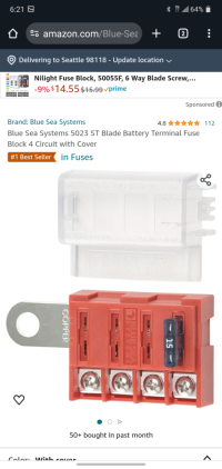
Or, trade the remote inline fuse for a battery mounted fuse. Then you have no unprotected wiring.
Screenshot_20240415-182142.png
 
Last edited:

Nick J

Contributing Partner
Moderator
Blogs Author
I've posted these a few times and I still like them. It provides a negative bus, high amp bus and standard blade fuses all in a small footprint. If you can locate it within 7" of the + terminal, you don't even need an additional fuse.

Blue Sea Systems 7748 SafetyHub 150 Ignition Protected Fuse Block
https://a.co/d/eCJuXgY
 

gareth harris

Sustaining Member
Kenneth is spot on. I have had a wire come loose and short circuit on the engine block, and then melt its way through the starter cable, with the first alert being the sound of the starter turning along with the cabin filling with smoke. The solution was to run the starter cable through a 100A circuit breaker, which is not standard procedure but it worked.

If, as it appears, every circuit is fused at the panel then the extra fuse is counterproductive since it creates more unprotected wire rather than less, and, as Kenneth has pointed out, that unprotected wire is flapping around above the battery negative terminal. The extra fuse would only be necessary if the fuse panel were somewhere else in the boat and there were a long run of wire to get to it.

Nigel Calder writes some confusing things sometimes, and does not get everything right (I say that as a physicist who has wired some albeit small components on a tokomak nuclear fusion reactor); the important point is that every circuit needs to be on a fuse in case of either a malfunction in an electrical component or a short circuit developing due to damage to the wiring. The size of the fuse is determined by the maximum current that is going to run through the circuit as determined by the component it feeds. The size of the wiring is determined by the voltage drop that will occur when that current runs along the length of the circuit.

Either run a secured wire straight from the battery terminal to the fuse panel, which is legal as per ABYC since it is less than a 7" run as Nick has pointed out, or better still take Kenneth's suggestion, which pretty much eliminates any risk, of a fuse right on the battery terminal (and then make sure the wire from it to the fuse panel is secured).

Gareth
Freyja E35 #241 1972
 
Last edited:

southofvictor

Member III
Blogs Author
Yeah, but it's in the wrong space. The 9-12 inches of wire between the battery and the inline fuse is unprotected and unsecured (especially the portion that's draped over the battery's neg post (chafing here would cause an unprotected short).

I'd move the inline fuse to the left of that ground block:
Good idea on placement and I wonder why it wasn’t done that way. What would give the tech the idea to go back and forth across all that space instead of making the cleanest line between the two ends?

In the tech’s defense I think what you see draped over the battery negative is Jeff’s drawing showing the connection between the orange wire and the red coming off the battery. It’s too long and it’s unsecured, but I think it runs behind the battery and not over the top of it.

Somebody I know with a lifetime of experience on boats recently said he’s never finished a project without immediately realizing he could have done something differently and better :)
 
Top