Guest viewing is limited
- You have a limited number of page views remaining
- 16 guest views remaining
- Register now to remove this limitation
You are using an out of date browser. It may not display this or other websites correctly.
You should upgrade or use an alternative browser.
You should upgrade or use an alternative browser.
Do we trust the E38's 40yr old AC and DC breakers?
- Thread starter Vtonian
- Start date

Our occasional "test" seems to occur about every other winter when I momentarily forget and operate the shop vac after having the AC space heater on for a while. That "outlet" circuit has a 15 amp breaker, and, after a couple seconds it opens/trips.
Cabin gets real quiet; realization occurs.
Cabin gets real quiet; realization occurs.

peaman
Contributing Partner
A basic receptacle tester is a great tool to have to make sure all of your receptacles are connected properly. Easy to use, just plug it in and then compare the lights with what's shown on the label. Also handy for checking which receptacles are connected downstream of a GFCI receptacle.

bsangs
E35-3 - New Jersey
You know, I actually own one of those from Klein. Will give it a go. Thanks for the rabbit hole fellas. Better than going outside to clear 25" of snow.A basic receptacle tester is a great tool to have to make sure all of your receptacles are connected properly. Easy to use, just plug it in and then compare the lights with what's shown on the label. Also handy for checking which receptacles are connected downstream of a GFCI receptacle.

Vtonian
E38 - Vashon
Update:
I did the math and think going with the new panels that I *want* would cost the best part of $1k, vs my idea of supplementing the originals with new breaker and fuse blocks. I've bled out already on this project, which includes updating all of the obvious bad wiring things, going house LFP and updating the solar. FWIW, the solar update is only partly about the improved yield, it's probably 75% because the current ones were installed on the bimini in a way that blocks my view of the main trim while standing at the helm, so I'm constantly ducking out to see that. The PO must have been short. The new panels are smaller, so can be mounted about a foot farther aft.
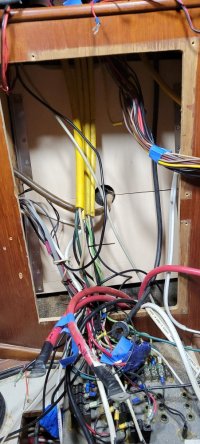
Also, since committing to the wiring update, I've cut open the already pretty trashed cabinet face and installed a back board for mounting the new gear, with a plan for a double hinged, fold down door to remount the original panels in, so for me, that's the heavy lifting and if I need or want to go to new panels later, it'd be almost a plug and play operation, aside from probably making a new door but that's the easiest part of the job, IMO.
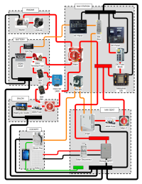
Anyway, here's my current iteration of my simplified wiring diagram (I could probably spend another 2 weeks tinkering on it but it's not getting any wiring done...), if anyone has a comment to improve or correct it, or a question about it, I'd appreciate it. So far, nobody has come up with why my concept is actually dangerous, other than being hypothetically not as good as new panels, so I think I'm going to go with it. It will *definitely* be a vast improvement over the stuff that's in there now.
Thanks again, I couldn't do it without y'all
I did the math and think going with the new panels that I *want* would cost the best part of $1k, vs my idea of supplementing the originals with new breaker and fuse blocks. I've bled out already on this project, which includes updating all of the obvious bad wiring things, going house LFP and updating the solar. FWIW, the solar update is only partly about the improved yield, it's probably 75% because the current ones were installed on the bimini in a way that blocks my view of the main trim while standing at the helm, so I'm constantly ducking out to see that. The PO must have been short. The new panels are smaller, so can be mounted about a foot farther aft.
Also, since committing to the wiring update, I've cut open the already pretty trashed cabinet face and installed a back board for mounting the new gear, with a plan for a double hinged, fold down door to remount the original panels in, so for me, that's the heavy lifting and if I need or want to go to new panels later, it'd be almost a plug and play operation, aside from probably making a new door but that's the easiest part of the job, IMO.
Anyway, here's my current iteration of my simplified wiring diagram (I could probably spend another 2 weeks tinkering on it but it's not getting any wiring done...), if anyone has a comment to improve or correct it, or a question about it, I'd appreciate it. So far, nobody has come up with why my concept is actually dangerous, other than being hypothetically not as good as new panels, so I think I'm going to go with it. It will *definitely* be a vast improvement over the stuff that's in there now.
Thanks again, I couldn't do it without y'all

It takes a while to look at someone's schematic (even a well-done on like yours), and evaluate all the in's & out's of the design. So here are just some cursory comments:if anyone has a comment to improve or correct it, or a question about it, I'd appreciate it.
The original EY systems (and it looks like yours as well) rely on the battery switch being set to 1/2/or ALL to prevent frying the alternator regulator when the engine is running. Nothing wrong with this--it works because you can't start the engine without the switch being set properly. But, as a safety, some people wire the alternator output directly to the house bank (with current protection), to remove the liability of the battery switch. A second alternative is to install a alternator protection device, which absorbs the surge that occurs if the battery switch is set OFF with the alternator running.
Second, I think your 300A/400A fuses are too large. Ampacity charts for DC battery cables typically show limits of 250A for 1/0 cable and 300A for 2/0 battery cable. So, 400A would be too high for those cables (and, 400A*12V = 4800 W, which is more power than most domestic kitchen ovens consume!). But, I'm NOT saying drop the fuse rating to match the capacity of your battery cables (which is the typical school of thought for wiring). Rather, I'd suggest computing the max draw your boat should ever consume and fuse to something just above that level. For most of us, the max draw occurs during engine start or windlass operation. I've heard our starters draw about 80A. Concurrently, you may be running the glow plugs (20A), lighting (5A), and electronics (3A). So, I can't see how you ever get above a 120A draw in normal operations (windlass and AC inverter excluded). Why not fuse for something just above that? Most fuses have are built to handle temporary exceedances of their rating.
Here's the AI summary on MRBF type battery fuses (you may be using a different type):
MRBF (Marine Rated Battery Fuse) fuses are fast-acting, typically blowing in 0.01 to 0.1seconds during a dead short (extremely high current). For overloads, they follow a time-current curve: at 200% of the rated current, they may take several seconds to minutes to blow. They are designed to withstand brief inrush currents (e.g., 0.5s) while protecting against sustained overloads. Key considerations for MRBF fuse trip times include:
- Instantaneous Short: Under extreme short-circuit conditions, they act almost immediately.
- Overload (2x rated): At double the rated current, they can take anywhere from 10 seconds up to 10 minutes to blow, depending on the specific model and thermal conditions.
- Inrush Current: They are designed to handle, for instance, a 5X current surge for roughly 5 sec for motors and 3 sec for other loads.
peaman
Contributing Partner
It looks like when your primary battery switch is "off", your solar charger output will not be going to storage, but will be putting power to your DC panel and other loads. Typically, you would want solar energy to go to storage whenever available.if anyone has a comment to improve or correct it, or a question about it, I'd appreciate it.
You might want to review your fuse sizes. The diagram shows a 300A fuse on a 100Ah battery. Fuses function to protect downstream wiring, so a 300A fuse should feed a conductor capable of safely passing 300A current, which is probably bigger than needed. Size the fuse for the load and not for the source.
Here is a good wire sizing chart.

Drewm3i
Marine Surveyor
@Vtonian If you read the instructions for the solar smart battery charger (that controls the charge input from the panels), it will probably tell you to wire it straight to each battery banks with proper fusing (usually around 10 amps). That is what I have done in the past and what I would recommend. I can see no good reason to run any modern (i.e. smart) battery charger connections through a main battery switch--and switches also have circuitry limitations. If not in use over long periods, you can either use it as a trickle charger or simply disconnect the terminals.
Another device that should bypass the battery switch (IMO) is the main bilge pump (if automatic as in an internal float switch) or float switch so you don't have to leave power switched on when away from the boat to run a bilge; if you have a high water alarm, I would recommend the same.
In short, your electrical revamp is a bit too complicated for my liking with too many breaks in the circuit for fuses and other devices that will over time lead to complications and electrical gremlins. I don't think the basic Ericson Yachts electrical system is too bad and I would recommend mostly sticking to it while integrating the charging control and ventilation changes necessary for a lithium house bank. ABYC does recommend fuses on the DC positive main electrical cables from/to the battery switch within 7" of the battery terminals, but in practice I almost never see them on any boat, including everyone I have owned (12), and the cables are so large that they can almost always carry the current necessary to the main DC engine breaker (common on almost all powerboats), etc. In my opinion, it is usual a good idea to preserve as much of the original design as possible--making improvements where needed--as the manufacturer typically does know what they are/were doing.
Thus, I would think carefully if such a mod is needed as you at each fuse/breaker junction you are potentially introducing another failure point as you are disrupting a continuous circuit of wire and introducing a connection which will have to be preserved from corrosion and/or loosening up via vibration over time. Thus, I would typically recommend to follow the equipment manufacturer's recommendations (for whatever you are installing) as they tend to be conservative in nature--designed to not only prevent fire, but protect sensitive equipment.
Another device that should bypass the battery switch (IMO) is the main bilge pump (if automatic as in an internal float switch) or float switch so you don't have to leave power switched on when away from the boat to run a bilge; if you have a high water alarm, I would recommend the same.
In short, your electrical revamp is a bit too complicated for my liking with too many breaks in the circuit for fuses and other devices that will over time lead to complications and electrical gremlins. I don't think the basic Ericson Yachts electrical system is too bad and I would recommend mostly sticking to it while integrating the charging control and ventilation changes necessary for a lithium house bank. ABYC does recommend fuses on the DC positive main electrical cables from/to the battery switch within 7" of the battery terminals, but in practice I almost never see them on any boat, including everyone I have owned (12), and the cables are so large that they can almost always carry the current necessary to the main DC engine breaker (common on almost all powerboats), etc. In my opinion, it is usual a good idea to preserve as much of the original design as possible--making improvements where needed--as the manufacturer typically does know what they are/were doing.
Thus, I would think carefully if such a mod is needed as you at each fuse/breaker junction you are potentially introducing another failure point as you are disrupting a continuous circuit of wire and introducing a connection which will have to be preserved from corrosion and/or loosening up via vibration over time. Thus, I would typically recommend to follow the equipment manufacturer's recommendations (for whatever you are installing) as they tend to be conservative in nature--designed to not only prevent fire, but protect sensitive equipment.
Since I do understand only some of the wiring & device details under discussion, I can only reiterate what surveyors have told me over the decades concerning safety. Always remember that the large red 1-2-All (as usually labeled) Master Switch has a fundamental purpose to fulfill. In case of smoke and/or fire, you need a way to quickly de-energize all circuits in the boat until the fire is out.
Admittedly I do have a couple of low-amp sensor wires direct to our battery, the wire from the charger, and (at the insistence of the manufacturer of our furnace) the lead to the furnace. Everything else is, as EY did, wired thru breakers on the main DC panel. Thanks to Blue Seas and their clever fuse bank that bolts to a positive battery terminal, allowing these to be fused much closer than 7 inches.
We do also have a newer hi-amp circuit breaker within a few inches of each battery bank. I do not recall the amperage off hand, but these take the place of those $$$ fuses that we opted out of.
When we are away from the boat, the only DC breaker that stays on 24/7, is for the Bilge Pump(s).
In the summer the Refrigerator is also on all the time, in case of a need for cold water, pop or beer...
Admittedly I do have a couple of low-amp sensor wires direct to our battery, the wire from the charger, and (at the insistence of the manufacturer of our furnace) the lead to the furnace. Everything else is, as EY did, wired thru breakers on the main DC panel. Thanks to Blue Seas and their clever fuse bank that bolts to a positive battery terminal, allowing these to be fused much closer than 7 inches.
We do also have a newer hi-amp circuit breaker within a few inches of each battery bank. I do not recall the amperage off hand, but these take the place of those $$$ fuses that we opted out of.
When we are away from the boat, the only DC breaker that stays on 24/7, is for the Bilge Pump(s).
In the summer the Refrigerator is also on all the time, in case of a need for cold water, pop or beer...
Last edited:
Vtonian
E38 - Vashon
Excellent, folks. Thank you. I'm going back over the manuals to get correct specs/instructions now.
Trying to sort out all the permutations involved has been a fun, interesting challenge. Between the original EY wiring, all the changes since, and the rapid evolution of the solar/LFP/inverter/charger technologies involved, at times I feel like a revolving ass hat but the goals are to 1) fix the boat (dead batteries), 2) fix the dangerously bad things, 3) update to modern technology where there's ROI, and 4) get back to sailing (which is really #1).
But a few quick notes:
@ Kenneth K:
The main battery switch turns on/off both banks simultaneously but does not combine them (except in an emergency). That is supposed to cover the need for a way to kill everything at once if needed. It also keeps the AGM and LFP isolated, aside from the controlled charging through the Orion XS DC/DC charger. In this configuration, the danger to the alternator if the BMS in the LFP decides to shut it down is mitigated by the alternator only connected to and charging the AGM, with LFP charging from the AGM through the Orion as needed. The performance hit is the Orion doesn't allow as much charging as the LFP can take, but I think my use pattern can work with that.
I've considered installing an alternator protector. I'm pretty confident the Orion will cover the LFP BMS shut off issue but agree, someone shutting off the main switch is not covered in this plan. I saw a ABYS/Victron video that talked about having a fuse and shut down near every battery or even remote in the cockpit, which is why I have a switch at the house bank, but that does assume that I or someone trained will be around in an emergency.
The 400A fuse I'm showing on the house bank is what the PO had already installed for 5 - 100Ah AGM batteries (now dead). I assumed he must have had a reason that I'd discover as I learned more. Guess not. Good call, I'll read the manuals, do the calcs and revise.
@ peaman:
You're right, and that is the way the PO had it wired, with solar direct to the house bank (but without a disconnect). I need to get that connected to the house bank again, otherwise what's the point of having solar? Dead batteries when you show up to the boat? Pshaw! Also, fuse sizes, yep.
@ Drewm3i:
My Renogy MPPT is 40A, and is wired with 8ga wires, which is why I went with a 40A disconnect. IIRC, it has a 20A max discharge, and I'd planned to add a 30A breaker on panel side of it. This diagram was intended mostly for keeping track of what the device mounting space/layout requirements were and figuring out what of the existing wiring could be reused vs added to, but in fact you've pointed out the now obvious fact I've gone too far without adding in significant details like that fuse.
The bilge pump does already bypass the panels and will continue to.
I also feel it's getting complicated, but I've had so many inputs about ABYC recommendations that I'm trying to compromise between their vender funded overkill (IMO), their truly smart reqs, and what's practical in the context of this boat at this time. Striving for progress, not perfection. Hadn't thought about ventilation for the LFP, or read the manual yet, but great call, that could be bad.
@ Loren Beach:
Yes, I'm using the BS terminal fuses, excellent kit. And yes, I do have a couple similar 24/7 loads, just haven't gotten to doping those out yet.
@ everyone:
Thanks again so much for your input. Just the process of budgeting, sourcing, ordering and tracking all this stuff is bigger than I thought. I usually work this kind of project scope size in IT networks or residential construction, so kind of thought this'd mostly fall into the same old hat, but no. Boat wiring, lithium, solar, galvanic gremlins, etc are really all pretty new to me and I can't wing them on the fly. It takes a fleet...
More later.
Trying to sort out all the permutations involved has been a fun, interesting challenge. Between the original EY wiring, all the changes since, and the rapid evolution of the solar/LFP/inverter/charger technologies involved, at times I feel like a revolving ass hat but the goals are to 1) fix the boat (dead batteries), 2) fix the dangerously bad things, 3) update to modern technology where there's ROI, and 4) get back to sailing (which is really #1).
But a few quick notes:
@ Kenneth K:
The main battery switch turns on/off both banks simultaneously but does not combine them (except in an emergency). That is supposed to cover the need for a way to kill everything at once if needed. It also keeps the AGM and LFP isolated, aside from the controlled charging through the Orion XS DC/DC charger. In this configuration, the danger to the alternator if the BMS in the LFP decides to shut it down is mitigated by the alternator only connected to and charging the AGM, with LFP charging from the AGM through the Orion as needed. The performance hit is the Orion doesn't allow as much charging as the LFP can take, but I think my use pattern can work with that.
I've considered installing an alternator protector. I'm pretty confident the Orion will cover the LFP BMS shut off issue but agree, someone shutting off the main switch is not covered in this plan. I saw a ABYS/Victron video that talked about having a fuse and shut down near every battery or even remote in the cockpit, which is why I have a switch at the house bank, but that does assume that I or someone trained will be around in an emergency.
The 400A fuse I'm showing on the house bank is what the PO had already installed for 5 - 100Ah AGM batteries (now dead). I assumed he must have had a reason that I'd discover as I learned more. Guess not. Good call, I'll read the manuals, do the calcs and revise.
@ peaman:
You're right, and that is the way the PO had it wired, with solar direct to the house bank (but without a disconnect). I need to get that connected to the house bank again, otherwise what's the point of having solar? Dead batteries when you show up to the boat? Pshaw! Also, fuse sizes, yep.
@ Drewm3i:
My Renogy MPPT is 40A, and is wired with 8ga wires, which is why I went with a 40A disconnect. IIRC, it has a 20A max discharge, and I'd planned to add a 30A breaker on panel side of it. This diagram was intended mostly for keeping track of what the device mounting space/layout requirements were and figuring out what of the existing wiring could be reused vs added to, but in fact you've pointed out the now obvious fact I've gone too far without adding in significant details like that fuse.
The bilge pump does already bypass the panels and will continue to.
I also feel it's getting complicated, but I've had so many inputs about ABYC recommendations that I'm trying to compromise between their vender funded overkill (IMO), their truly smart reqs, and what's practical in the context of this boat at this time. Striving for progress, not perfection. Hadn't thought about ventilation for the LFP, or read the manual yet, but great call, that could be bad.
@ Loren Beach:
Yes, I'm using the BS terminal fuses, excellent kit. And yes, I do have a couple similar 24/7 loads, just haven't gotten to doping those out yet.
@ everyone:
Thanks again so much for your input. Just the process of budgeting, sourcing, ordering and tracking all this stuff is bigger than I thought. I usually work this kind of project scope size in IT networks or residential construction, so kind of thought this'd mostly fall into the same old hat, but no. Boat wiring, lithium, solar, galvanic gremlins, etc are really all pretty new to me and I can't wing them on the fly. It takes a fleet...
More later.

When we are away from the boat, the only DC breaker that stays on 24/7, is for the Bilge Pump(s)
I always wondered why Ericson didn’t have a bilge pump circuit separate from the main DC panel. I just rewired my bilge pump to be isolated from the DC panel and main battery switch thinking that I wanted those de-powered when not at the boat. The bilge pump now is connected directly to the battery (properly fused) and has a dedicated on-off switch at the chart table. Likely overkill, but with the somewhat janky wiring others have noted I feel more comfortable with this arrangement.
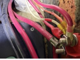
Incidentally this is what the backside of the battery switch looks like. I don’t like that many wires connected to it and feel like there is room for improvement with some bus bars. I need to add some battery fuses too, so this will be an upcoming project.

Vitonion, Here are some recommendations I see after looking at your plan. Most are just preferences, with the exception of some fusing
Inverter Location
What’s the purpose of the DC fuse block between the current position of the safety hub and DC panel? If it’s for panel lights and other minor items, I wouldn’t put it series with the main DC panel feed. Just run it off the bus on the back of the panel
AC to DC negative / neutral tie
It’s probably just a drawing thing, but you should only have a single location where the AC neutral and DC negative are tied together and it should be at the boats main ground bus. It should be well labeled and easily identifiable.
DC Battery shunt
You may not be installing a battery monitor today (probably because the WattCycle has a good app and it’s a good candidate do at a later time), but if you think you will eventually add one, now’s the time to plan for the shunt location(s).
Solar charger
Inverter Location
- If you have a water heater or any other High power AC devices on the boat or plan to install one, putting a 2000W inverter/charger between your shore power plug and main distribution panel is not ideal because you don’t want to accidentally run those off the battery. In your current configuration, if you lost shore power and had any of those devices on, they would quickly deplete your 314ah battery.
- I would run your main AC panel off the main 30 amp double pole breaker then install a 20 amp double pole breaker on the distribution side feeding your inverter/charger. Then have a sub panel or at leas a single breaker on the distribution side of the inverter feeding only your outlets.
- I would also run the DC connection before the main switch. You already are planning for an inverter/charger disconnect switch, so you can safely connect this to the non-switched bus. While you’re away, you can switch off the inverter function, DC main switch and still have your house bank charging.
- You currently don’t have any non switched circuits other than the DC to DC charger. Bilge pumps, chargers, and stereo memory circuit are good items to place before a battery switch so they don’t accidentally get turned off.
- I would move the safety hub between the Class T fuse and the switch (or after if the switch is only used as a safety isolation switch) on your house battery and buy another one for the start battery. You’re going to need some kind of buss bar on the start battery with 3 cables connecting anyway, might as well use the safety hub and get fusing as well. That would also eliminate the need for the 2 60 amp breakers on either side of the DC to DC charger.
What’s the purpose of the DC fuse block between the current position of the safety hub and DC panel? If it’s for panel lights and other minor items, I wouldn’t put it series with the main DC panel feed. Just run it off the bus on the back of the panel
AC to DC negative / neutral tie
It’s probably just a drawing thing, but you should only have a single location where the AC neutral and DC negative are tied together and it should be at the boats main ground bus. It should be well labeled and easily identifiable.
DC Battery shunt
You may not be installing a battery monitor today (probably because the WattCycle has a good app and it’s a good candidate do at a later time), but if you think you will eventually add one, now’s the time to plan for the shunt location(s).
Solar charger
- Does your MPPT charger have an internal DC protection? If not, you should add a breaker or fuse on the output cable.
- If you’re already going down the Renogy MPPT route, take a look at their onboard battery charger. It’s a DC to DC charger that goes both directions and built in MPPT. It could replace the Orion DC to DC charger, MPPT, and 10 amp starter charger with a single device. I have one on our boat and it’s functioned great so far. I don’t currently have any solar panels, but this offers a simple path to add them in the future.
- https://www.renogy.com/collections/...-50a-dc-dc-on-board-battery-charger-with-mppt
- I really like the ability to independently switch my house and starter battery banks and the dual circuit battery switch you have won’t allow you to do that. Like others have mentioned, It’s nice to have items like a refrigerator running while you’re away. These are different than the 24 hour circuits mentioned under the non switched section above. If you would like to keep these items on, it’s nice to be able to turn off the starter while you’re away as an added security feature. I really like Blue Sea system’s Dual bank battery management panel (8280). It is more money than the dual circuit switch you have in the drawing, but I think it’s well worth it. It also allows you to turn off the house bank without disconnecting the alternator.
- https://defender.com/en_us/blue-sea...JilNxPKZaJAMJsx45scApwV7FROQCJGqZgHiL8UVJha9c
I'd add to that list: battery monitor and any bluetooth devices that help manage your electrical (or other) system (my Victron MPPTs get bluetooth info from a temp/volt sensor mounted on the house bank).Bilge pumps, chargers, and stereo memory circuit are good items to place before a battery switch
Also, great, comment about adding space for a shunt. Shunts have to be inserted into a main battery cable and battery cables are difficult to relocate/re-terminate once installed.
Last edited:
peaman
Contributing Partner
My system has an "always on" fuse block connected to the house battery bank. That powers the bilge pump through a float switch, the shower sump pump through its man/auto panel, the clock function on the AM/FM/CD unit, and a 12V cigar lighter at the helm for charging a phone, for example. A separate always-on fuse is provided for the solar controller. When I bought the boat, there were fuses of various types scattered throughout the boat. Adding this, and another fuse block for the helm instruments, allowed me to "standardize" on blade type automotive fuses, with only a couple others out in the wild. The main bilge pump can also be controlled manually through a breaker on the DC panel when the batteries are switched on.I always wondered why Ericson didn’t have a bilge pump circuit separate from the main DC panel. I just rewired my bilge pump to be isolated from the DC panel and main battery switch thinking that I wanted those de-powered when not at the boat. The bilge pump now is connected directly to the battery (properly fused) and has a dedicated on-off switch at the chart table. Likely overkill, but with the somewhat janky wiring others have noted I feel more comfortable with this arrangement.
That's an excellent point about standardized fuse types. It's never fun to trace a circuit out only to find the blown fuse is the one type you don't have a spare for.allowed me to "standardize" on blade type automotive fuses, with only a couple others out in the wild.

It looks like you also addressed another pet peeve of mine, hidden in-line fuses. I cut all of them off and run the power leads back to known fuse blocks like you've done. Future you and any future owners are going to be happy you put in the extra effort.
Vtonian
E38 - Vashon
Yikes! So much great info...
@ bigd14:
My bilge pump was also wired by the PO with an on/off/auto switch in the quarter berth, which has been useful during the leaky times...
@ Nick J:
I will definitely revisit the placing of the inv/chg, great call about pointlessly draining batteries because of lost shore power. I'd been lulled into buoy boat thinking, only boat power is sketchy, shore power is 100%...
About AC main breaker functions, I'd been thinking the new 30A DP breaker on the shore power side would suffice as protection and service disconnect, then using the existing AC panel's main 'breaker'/switch as panel kill only, w/o new/additional breaker protections. Individual circuit protection would be from the new, in-line breaker block. Kludgy but in keeping with trying to cheap out on improving w/o perfecting with all new panels. Does that sound reasonable, or fall into the 'just because you can doesn't mean you should' category?
On placing the DC connection before the main switch, I'll think that through more, I'll need to work that out on paper, brain... overheating...
On non-switched circuits, hadn't thought about stereo. One came with the boat, new in the box, but I'd relegated that to Mr. Ferrari's philosophy, no radios in the world's greatest chariot. However, adding Christian's audio book to my ship's library has reminded me that anchoring is a different universe. Maybe...
On a second SafetyHub on the start bank side, drat! Great idea, especially if it can eliminate the 60A breakers for the Orion.
The new DC fuse block is there to take over protection duties from the antique panel breakers, which will now be used just for switching.
Excellent note about AC/DC neg/neut tie. Yes, not drawn but also yes, I could have overlooked that in the rush.
On DC shunts, I have one already from the PO that ran the Xantrex inv/chg and Renogy mppt panels. There isn't any reason to have more than one, is there?
On solar charger, yes, I'll be adding a breaker on output side, but !DRAT! again on suggesting the Renogy DC/DC charger. I don't recall why when researching them I looked at the Renogy but reluctantly opted to buy into the Victron universe, thinking it was probably inevitable. But you're absolutely right, if the Renogy can do all that, it's better, simpler, and also *cheaper*! 50A version on sale now on Amazon for $220, ordered and on its way.
Battery switching, cool panel but maybe in a future iteration. I will add a separate kill switch for the engine though, I can do that with current inventory (not a hoarder, but definitely a pack rat). Another good call.
@ Kenneth K:
Yes, I'm succumbing to blue tooth apps, but only if/as available included with the new gear. Will Prowse made the comment about if he needed to open an app to see what was going on, he must have done something wrong and I liked that attitude, I'm already buried in tech everywhere else in my life, I want to think about sailing as a refuge from it. That said, if it's already in there...
@ peaman:
Shower sump, hmmm, I've never found that, although never taken a shower (in the boat). I'll have to spelunk that.
12V lighter sockets, yes, on my only trip so far, with both adult daughters, charging was the thing we were least prepared for. I now have a half dozen different ways to charge stuff but hadn't thought about which should be always on vs switched. Good point.
Standardized/centralized fuses should be an outcome; I can think of at least one in-line fuse that is lurking out there.
@ everyone:
Thanks again, so much!
@ bigd14:
My bilge pump was also wired by the PO with an on/off/auto switch in the quarter berth, which has been useful during the leaky times...
@ Nick J:
I will definitely revisit the placing of the inv/chg, great call about pointlessly draining batteries because of lost shore power. I'd been lulled into buoy boat thinking, only boat power is sketchy, shore power is 100%...
About AC main breaker functions, I'd been thinking the new 30A DP breaker on the shore power side would suffice as protection and service disconnect, then using the existing AC panel's main 'breaker'/switch as panel kill only, w/o new/additional breaker protections. Individual circuit protection would be from the new, in-line breaker block. Kludgy but in keeping with trying to cheap out on improving w/o perfecting with all new panels. Does that sound reasonable, or fall into the 'just because you can doesn't mean you should' category?
On placing the DC connection before the main switch, I'll think that through more, I'll need to work that out on paper, brain... overheating...
On non-switched circuits, hadn't thought about stereo. One came with the boat, new in the box, but I'd relegated that to Mr. Ferrari's philosophy, no radios in the world's greatest chariot. However, adding Christian's audio book to my ship's library has reminded me that anchoring is a different universe. Maybe...
On a second SafetyHub on the start bank side, drat! Great idea, especially if it can eliminate the 60A breakers for the Orion.
The new DC fuse block is there to take over protection duties from the antique panel breakers, which will now be used just for switching.
Excellent note about AC/DC neg/neut tie. Yes, not drawn but also yes, I could have overlooked that in the rush.
On DC shunts, I have one already from the PO that ran the Xantrex inv/chg and Renogy mppt panels. There isn't any reason to have more than one, is there?
On solar charger, yes, I'll be adding a breaker on output side, but !DRAT! again on suggesting the Renogy DC/DC charger. I don't recall why when researching them I looked at the Renogy but reluctantly opted to buy into the Victron universe, thinking it was probably inevitable. But you're absolutely right, if the Renogy can do all that, it's better, simpler, and also *cheaper*! 50A version on sale now on Amazon for $220, ordered and on its way.
Battery switching, cool panel but maybe in a future iteration. I will add a separate kill switch for the engine though, I can do that with current inventory (not a hoarder, but definitely a pack rat). Another good call.
@ Kenneth K:
Yes, I'm succumbing to blue tooth apps, but only if/as available included with the new gear. Will Prowse made the comment about if he needed to open an app to see what was going on, he must have done something wrong and I liked that attitude, I'm already buried in tech everywhere else in my life, I want to think about sailing as a refuge from it. That said, if it's already in there...
@ peaman:
Shower sump, hmmm, I've never found that, although never taken a shower (in the boat). I'll have to spelunk that.
12V lighter sockets, yes, on my only trip so far, with both adult daughters, charging was the thing we were least prepared for. I now have a half dozen different ways to charge stuff but hadn't thought about which should be always on vs switched. Good point.
Standardized/centralized fuses should be an outcome; I can think of at least one in-line fuse that is lurking out there.
@ everyone:
Thanks again, so much!
About AC main breaker functions, I'd been thinking the new 30A DP breaker on the shore power side would suffice as protection and service disconnect, then using the existing AC panel's main 'breaker'/switch as panel kill only, w/o new/additional breaker protections. Individual circuit protection would be from the new, in-line breaker block. Kludgy but in keeping with trying to cheap out on improving w/o perfecting with all new panels. Does that sound reasonable, or fall into the 'just because you can doesn't mean you should' category?
If the picture in the drawing is the breaker block you're intending to use, this boarders on the dangerous side of kludgy. It looks like it's only rated to 32VDC https://www.bluesea.com/products/5050/ST_CLB_Circuit_Breaker_Block_-_6_Independent_Circuits.
If your existing panel doesn't support A or C series toggle style breakers maybe these will work:
I don't have any experience with them, but the specs look like they would work electrically. You'd have to double check the physical compatibility. Another thing to think about is the panel's indication lights.
In addition to a switch and circuit protection, panels often offer indication that the breaker is on and, in some cases, additional information like reverse polarity. If these are in bad shape and need to be replaced, you might find yourself closer in cost to replacing the panel.
I think it's commitment. The planning stage, especially for large projects, can go on for week. Weighing ideas, making sketches, conducting internet research, and price/spec comparisons can be endless. But once the tools come out, the project starts to take life. And with the old parts removed and the new holes are cut, there's no going back.there is something perversely satisfying about taking a saw to your boat. Revenge maybe?
Vtonian
E38 - Vashon
Agree 100%... although there being nothing so permanent as a functional temporary fix, the question is, when is the commitment met? The winds beckon...I think it's commitment. The planning stage, especially for large projects, can go on for week. Weighing ideas, making sketches, conducting internet research, and price/spec comparisons can be endless. But once the tools come out, the project starts to take life. And with the old parts removed and the new holes are cut, there's no going back.
@ Nick J, another good catch. Bad search filtering on my part I guess. I recall looking at the B/S 7214 and thinking they might be made to fit but didn't want to have to drill and counter sink the mounting screw holes (which would also desecrate the original labels).
That said, I haven't found any alternatives that can get the 4 AC breakers updated that'll run under ~$350 for a B/S 8099 panel w/main & 4 positions, plus the 4 20A breakers, so in keeping with Rube Goldberg theme, I think I'll measure those out and see if I can make them work, for ~$100 and $300 labor. ;-)
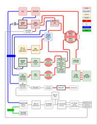
FWIW, I'm attaching the current, still in progress version of my wiring diagram effort to incorporate my best understanding of the good advice given here. I am still in the process of inspecting the existing wiring to make sure what I have to work with, and reading manuals on current and new equipment to try to confirm it'll work out. Pleasantly surprised to find how close the EYO E38 wiring diagram has been to actual. Also thoroughly enjoying being able to spend a little time on the boat nearly every day, although find I'm getting to bed around 4am, after playing with diagram software all night... I'm trying to find a way to represent it so a year from now, it'll be self explanatory to my visual way of thinking.