• Untitled Document

    Join us on March 28th, 7pm EDT

    for the CBEC Virtual Meeting

    EY.o March Zoom Meeting

    All EYO members and followers are welcome to join the fun and get to know the people you've met online!

    See the link below for login credentials and join us!

    March Meeting Info

    (dismiss this notice by hitting 'X', upper right)

E35-2 unusual hull deck joint

adam

Member III
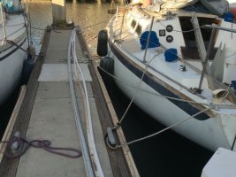
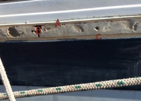
My hull deck joint seems to be leaking a bit, and when I pulled it apart I was surprised to find something completely different than the manual.

My previous boat had about a 3/4" outward flange where the deck and hull were put together.

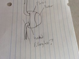
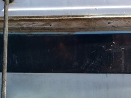
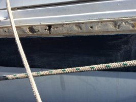
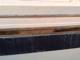
This E35-2 has almost no outward flange (7/32") and a 1" wide strip of wood between the two flanges.

I am considering dumping the rub rail completely and either grinding away the exterior or replacing the wood with some nicely varnished wood.

BUT, does anyone know how this boat is built?

Is it possible that this boat is completely different than the manual, the deck overlaps the hull in this boat, and the ~50 little machine screws that I removed are what holds the boat together?

attachment.php
 

Attachments

  • IMG_0145.JPG
    IMG_0145.JPG
    98.3 KB · Views: 352

Loren Beach

O34 - Portland, OR
Senior Moderator
Blogs Author
Message #5 describes the hull deck joint which is in the manual, and which was on my previous boat. That's what I expected to find when I pulled off the rubrail.

But the joint on this E35 is seems substantially different.

You will need to remove trim and examine the inside of the joint. It should be covered by a layer (or 2) of roving.

Loren
 

adam

Member III
In the photo above, I've removed everything including a section of the wood strip which was damaged.

The wacky part is that I can't even find the actual joint where the two halves of the boat were put together.

And I'll take a look with a coring bit if I have to, but first I'd like to wait a while and see if anyone has knowledge of how this other type of joint was assembled.
 

Guy Stevens

Moderator
Moderator
I don't think you are to the hull deck joint yet

Hard to tell from the photo, but I think the joint is under the piece that was holding the wood. On most of the ER boats they just have a rubber bumper where the wood is on yours. It normally slides or is hammered into the piece your wood is mounted into .

Guy
:)
 

adam

Member III
Thanks Guy.

My boat did have the hard plastic track and rubber bumper. I removed them while looking for leaks.

And the hard plastic track was screwed through the wood into the fiberglass.

What I'm really trying to figure out is if those 50 little machine screws could have possibly served a structural purpose, holding the boat together, or if they solely were there to hold on the rubrail?

attachment.php
 

Attachments

  • IMG_0149.JPG
    IMG_0149.JPG
    149.3 KB · Views: 319

Loren Beach

O34 - Portland, OR
Senior Moderator
Blogs Author
All those little screws are there to hold the trim on. Original was anodized aluminum, and someone in the past must have replaced it. Those screws do not hold the boat together.

LB
 

Christian Williams

E381 - Los Angeles
Senior Moderator
Blogs Author
The wood looks nonstandard, doesn't it?

Were deck/hull flanges ground off so a flat rub rail would fit?

(The flanges required a specialty rub rail--some in aluminum.)
 

toddster

Curator of Broken Parts
Blogs Author
Hard to see how that could have been done after the factory. Maybe somebody realized that sticking screws into the gap was stupid and would never last? Maybe only someone who was there could answer.
 

bigd14

Contributing Partner
Blogs Author
Page 28 of the 35-2 owners manual shows the typical hull deck joint with outward flanges. Unless the factory tried something wildly different, I would guess that the entire flange was ground off and routed to allow the wood piece to be inserted. That would explain the absence of a seam. The picture may be of the backside of the interior fiberglass strips bonding the hull and deck together from inside. It would be interesting to find out how thick that area is. If the joint was ground off, it seems like a lot of unnecessary work and would risk compromising the structure of the boat. Further investigation from inside is necessary.
 

Mark F

Contributing Partner
Blogs Author
I think I remember reading that some of the early 35-2's had a 1" wood filler at the deck joint to increase the headroom.
 

adam

Member III
I think I remember reading that some of the early 35-2's had a 1" wood filler at the deck joint to increase the headroom.

That seems exactly the case here.

The rubrail seems designed to protect the outward flange. As my boat effectively lacks that, is there any good reason not to just get rid of the rubrail, and have about 100 fewer holes in my boat?
 

adam

Member III
Mark, that link is super useful.

But the plot thickens.

Exucse my very crude drawing, but my joint seems to be built like this:

1. The rubber and plastic rub rail which is traditional to Ericsons.

2. Then a bit of wood trim.... I can't imagine this is at all structural as it's only maybe 1/4" wide at it's wisest. Maybe this was originally a spacer, but then ground down before installing the rub rail??

3. Behind that is something hard and fiberglass like. It may be the same stuff which is described in the manual as "seam fill". Anyone know what that was?

The two photos show a section I cleaned up a bit and what might be the exposed "seam fill" and another section which seems it was damaged and repaired inadequately with bondo (sigh).

I guess if that "seam fill" is at all fragile and subject to damage, I will definitely want to at some point soon glass over the entire thing.....

attachment.php
attachment.php
attachment.php
 

Attachments

  • IMG_0161.JPG
    IMG_0161.JPG
    92.6 KB · Views: 66
  • IMG_0159.JPG
    IMG_0159.JPG
    116.9 KB · Views: 68
  • IMG_0160.JPG
    IMG_0160.JPG
    128.4 KB · Views: 57

Christian Williams

E381 - Los Angeles
Senior Moderator
Blogs Author
This is a very interesting construction methods thread--or maybe I am just slow to understand it.

What are A and C? Is that fiberglass? It looks like end grain plywood, which seems unlikely.

What is behind the void at B--perhaps roving on the inside of the joint?

Fascinating that wood was used to raise the deck to gain headroom (Martin King, in the thread cited above).

I am wondering if the wood insert was just a spacer, with no structural role, and that the connection is the roving.

On my model the deck/hull flanges meet--but all the strength of th ejoint comes from the interior layers of overlapping roving (there are no through bolts or other metal connection).

]http://www.ericsonyachts.org/infoexchange/attachment.php?attachmentid=20474&stc=1[/IMG]
 

Attachments

  • 1970s Ericson rubrail.jPG
    1970s Ericson rubrail.jPG
    75 KB · Views: 218
Last edited:

Loren Beach

O34 - Portland, OR
Senior Moderator
Blogs Author
Whether they temporarily held the top and hull in alignment with screws thru the horizontal flanges while layers of roving were applied down the inside or added a layer of wood to slightly raise the deck -- while they applied a layer(s) of roving down the inside, final strength of the hull-to-deck would be the same. After the inside band of roving and resin kicks, the outer flanges were ground off and the joint covered with aluminum.
Note that the trim, whether original aluminum or later vinyl, is cosmetic.

Note B: there is an Ericson 34 or 35-3 somewhere in our area with no outside trim piece at all. I saw it up close at a local boat yard over a decade ago. The upper (painted) cove stripe was wide and covered a smooth area all the way along each side where they yard had glassed over the joint and faired it out.

Without the external joint cover, it took me a moment to realize it was an Ericson!
:)

Regards,
Loren

ps: in the picture above, A and C are just the cut-off edges of the deck and hull flanges. You are viewing the 'end grain' of the layers of cloth and resin for each of those pieces.
 
Last edited:

adam

Member III
This is a very interesting construction methods thread--or maybe I am just slow to understand it.

What are A and C? Is that fiberglass? It looks like end grain plywood, which seems unlikely.

What is behind the void at B--perhaps roving on the inside of the joint?

Fascinating that wood was used to raise the deck to gain headroom (Martin King, in the thread cited above).

I am wondering if the wood insert was just a spacer, with no structural role, and that the connection is the roving.

On my model the deck/hull flanges meet--but all the strength of th ejoint comes from the interior layers of overlapping roving (there are no through bolts or other metal connection).

]http://www.ericsonyachts.org/infoexchange/attachment.php?attachmentid=20474&stc=1[/IMG]

As Loren said, A and C are the end grain of the outward flange.

B seems to be a bad bondo "fix"'. Behind that void is nothing.... until the wood planking that lines the interior. That's very bad! And I don't see any easy way to remove the planking.

But that's just the damaged section. If you look at the other picture, B is something solid, and in the areas of the boat where I can access the back of it (bow, vberth, cockpit locker, etc) I see layers of fiberglass.
 
Last edited:

Christian Williams

E381 - Los Angeles
Senior Moderator
Blogs Author
I'll look tomorrow, but I think the cabin mahogany walls (the "ceiling") on my boat is screwed and plugged.

[...Yep. The bulkhead trim might have to come off too, but if the long ceiling planks have to be cut, the trim would hide the cut later.]
 
Last edited:

adam

Member III
With more poking around plus your help, I think I've figured this out.

1. They added a 1" block as a spacer to give the boat more headroom before fiberglassing the back.

2. The plastic rubrail no longer fit over the much wider flange.

3. So, they simply ground away most of the outward flange and wood.

4. Ironically, making the rubrail mostly unnecessary....
 
Top