• Untitled Document

    The 2024-2025 Fund Raising Season has Opened!

    EricsonYachts.org has opened the season for raising funds to support the expenses of the site. If you would like to participate, please see the link below for additional information.

    Thanks so much for your continued support of EricsonYachts.org!

    2024-2025 Fund Raising Info

E35/3 autopilot questions

Alan Gomes

Sustaining Partner
One thing a wheel pilot can't handle is waves on a reach, which are what makes all the work for a human helmsman. If the boat is caused to roll by a quartering sea, the hull form makes it turn powerfully as it rolls, and the little gizmo cannot compensate. Otherwise, though, wheel pilots works well if we remember to accommodate their needs.
This is certainly true by the nature of the case, since a human helmsman can anticipate what is coming vs. reacting to what is taking place. But it's also true that not all autopilots are created equal in the way they handle this.

My Pelagic autopilot, which granted is a tiller pilot vs. a wheel pilot, does a remarkably good job in surfing down waves on a reach--close to as good as a human helmsman and plenty good enough most of the time. As an apples-to-apples comparison, there is a world of difference between the Pelagic and the Raymarine ST-2000 tiller pilot. Not only is the actuator far more powerful than the anemic motor with plastic gears in the Raymarine, but the 9-axis gyro in the Pelagic adapts to the sea conditions and boat motion quite smartly. It's actually pretty impressive. I really get a kick out of watching it do its thing on my beam to broad reaches back from the Isthmus to San Pedro.

All the comments about sail trim are, of course, spot on. Autopilots, even at their best, cannot overturn the laws of physics. If a human helmsman is finding the boat out of balance and difficult to control, an autopilot will certainly not find it any less so.
 

Pete the Cat

Sustaining Member
I would advise against using a common circuit for both the wheel drive and the NMEA network. My autopilot craps out with some frequency (simply stops driving, usually because it is overpowered by wind) and my normal solution is to treat it like a Windows PC. I turn it off and back on several different ways. Power down the drive, flip the circuit breaker, even pull the fuse contained in the ACU. I have an panel breaker, then an in-line fuse for the ACU, then the ACU itself has an on-board 10am blade fuse.

Pulling and reinstalling the in-line fuse between the panel and ACU controller usually works when other attempts have failed.

You shouldn't need to take down the NMEA (Seatalk) network at the same time while you are messing with the autopilot.

Once you go to the trouble of bringing a Seatalk cable to your helm for the control head, that same cable can carry data from your wind instruments sounder, etc.. You might well want all of that stuff to operate independently of your wheel pilot. But it can take 30-60 seconds for the network to boot up if you have to shut it down.

For people who want a stand-alone autopilot, the multiple power sources can be annoying/frustrating. But the paradigm that all the manufacturers are following now is that one should be running a network. You need the 5amp circuit for the network and the 10amp to turn the steering wheel.

$.02
I might be wrong here, but one of the things that Raymarine always seemed to have a problem with, was keeping the instrument and head circuits (NMEA) from powering the autopilotdrive motor if the direct motor feed from a separate circuit shorted for some reason. I have had this dilemma on my old linear drive Raymarine (operating off the 60+ system) and the EV-1 off the backbone. So I elected to put it all on one circuit. I have not had a problem with tripping. The draw of the control unit and computer is next to nothing when the autopilot is not engaged and it is always ready to go. I would like to be corrected if someone has a better understanding. I think I understand their problem: once they put 12V into the head unit, it finds its way to the motor through the control and computer circuitry--but those are tiny wires that should not be carrying that kind of amperage to operate the motor. Maybe I am missing something in my understanding of the circuit.
 

goldenstate

Sustaining Member
Blogs Author
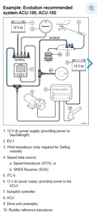
1674147944271.png

I followed this diagram for the most part.

In my wheel pilot the power that the drive motor utilizes does not pass through the P70 control head.

The power that turns the steering wheel comes from the ACU, which itself must take instructions from the NMEA network.
 

peaman

Sustaining Member
Can anyone chime in on what they did re fusing for their systems?
My autopilot is the only Raymarine product I have, and having heard about network conflict issues, I wanted to be able to separate the SeaTalk net from the rest of my NMEA2K network. The ACU-100 is mounted on a backboard along with the SeaTalk block and a small terminal block. A 10A breaker supplies power to the terminal block which powers the ACU-100 and a fused supply to the SeaTalk block. I have had no issues with having both AP motor and SeaTalk network served from the same terminal strip.

But I also wanted to be able to connect the SeaTalk net to the main NMEA2K net, so I connected the two using a SeaTalk backbone cable terminated with a standard N2K connector, with the power wire left unconnected. I have had no problems with connecting the two nets in that manner, other than the expected "language" differences between Raymarine and B&G.
 

goldenstate

Sustaining Member
Blogs Author
Regarding the Raymarine wheel pilot becoming overpowered, a common complaint, allow me to comment that like any self-steering they are hugely dependent on sail trim.

A wheel pilot requires weather helm to be reduced or eliminated. This means shortening sail, sometimes a lot. Off the wind, it means close attention to the mainsail, which is often overtrimmed when self-steering. If the main is allowed to luff a bit, that effectively reduces the difficulty of the little motor to steer the boat. This is revealed by the simple test of feeling the wheel on a broad reach in 15 knots. With our fin keels and spade rudders such sailing requires attention, often quite a lot of it, with determined corrections to keep on course, which we take as the fun of reaching on a sparkly day.

But let the mainsail out more, let it luff a bit or reef it, and the helm corrections required are radically reduced. And the wheel pilot works again, without beeping and turning itself off. Similar strategies are necessary with wind vanes, which are also sensitive to sail set, and often require reduced sail area compared to hand steering.

One thing a wheel pilot can't handle is waves on a reach, which are what makes all the work for a human helmsman. If the boat is caused to roll by a quartering sea, the hull form makes it turn powerfully as it rolls, and the little gizmo cannot compensate. Otherwise, though, wheel pilots work well if we remember to accommodate their needs.
I agree with all of these observations regarding the importance of sail trim.

The wheel pilot is like a small obedient child when it comes to steering the boat. It works fine, until it cries when it can no longer do the job. If I scurry around and reef and trim and luff, I can let the child drive again.

Then at some point it may be helpful to ask, is the child driver working for me, or am I working for the child driver?

I like my wheel pilot very much for motoring in straight lines.

As soon as I'm in 10+ knots my Aries is far more serviceable and easier to tune.
 

gabosifat

Member III
Great replies, thanks. Opened up the YSS pedestal to run the new wires and remove the old (will use the old data Marine wires to chase the new ones up). The old wires seem to go Willynilly through the pedestal column - close to the chain etc. Couldn’t find any conduit specifically for running wires that would keep it out of the mechanical gear. Others experience or advice doing this?
Much appreciated,
Steve
 

Nick J

Contributing Partner
Moderator
Blogs Author
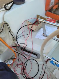
I ran my wires up the pedestal guard rails. It's tight, but it does remove it from the mechanical gear. I'm planning on running the compass light back down the other rail and into the top of the pedestal. The thick black cable is the NMEA backbone and the thinner one is the ground. There's a 12 AWG for the autopilot and two 14 awg for the compass light and USB charger. I later ran the connection to the compass (I have the older Raymarine wheel pilot) through the same leg.

20220627_201540.jpg
 

peaman

Sustaining Member
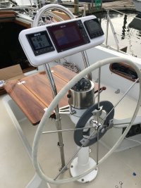
Great care should be taken in running wiring through the pedestal. My boat had a rat's nest of wires for the NMEA0183 instruments which passed through the pedestal and then they were woven in and out of the pedestal guards. I decided to re-do the whole rig and eliminated all wiring within the pedestal except for the compass light and AP motor. Other wiring for chart plotter, radar, and AP was run through a new pedestal guard into a NavPod. If your pedestal is opened completely, you might be able to insert a section of PVC tubing, or similar, to provide a protective conduit for wiring. The corrugated hose used sometimes used for small bilge pumps like Trident 120 in 3/4" might work well.

IMG_2921.JPG
 

Nick J

Contributing Partner
Moderator
Blogs Author
Great care should be taken in running wiring through the pedestal. My boat had a rat's nest of wires for the NMEA0183 instruments which passed through the pedestal and then they were woven in and out of the pedestal guards. I decided to re-do the whole rig and eliminated all wiring within the pedestal except for the compass light and AP motor. Other wiring for chart plotter, radar, and AP was run through a new pedestal guard into a NavPod. If your pedestal is opened completely, you might be able to insert a section of PVC tubing, or similar, to provide a protective conduit for wiring. The corrugated hose used sometimes used for small bilge pumps like Trident 120 in 3/4" might work well.

View attachment 45600
Wow, this is exactly what I would like to do. Did you have the new guard custom made or did you buy an Edson guard?
 

Christian Williams

E381 - Los Angeles
Senior Moderator
Blogs Author
wires seem to go Willynilly through the pedestal column

Pedestal-guard wire run is better. Just drill a hole in the cockpit floor under one guard base. I do have compass lamp wires in the pedestal, but that's all.

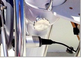
Drill access holes in the guard base tubes for wire entry, using the usual stainless tube drill technique of nail punch, then gradually increasing bit sizes and lots of pressure and oil. Sometimes a piece of plastic hose can be fitted into the tube hole to protect the wire.

2 tube Capture.JPG
 
Last edited:

goldenstate

Sustaining Member
Blogs Author
Great care should be taken in running wiring through the pedestal. My boat had a rat's nest of wires for the NMEA0183 instruments which passed through the pedestal and then they were woven in and out of the pedestal guards. I decided to re-do the whole rig and eliminated all wiring within the pedestal except for the compass light and AP motor. Other wiring for chart plotter, radar, and AP was run through a new pedestal guard into a NavPod. If your pedestal is opened completely, you might be able to insert a section of PVC tubing, or similar, to provide a protective conduit for wiring. The corrugated hose used sometimes used for small bilge pumps like Trident 120 in 3/4" might work well.

View attachment 45600
That's a pretty table!
 

peaman

Sustaining Member
Did you have the new guard custom made or did you buy an Edson guard?
It is a Navpod guard with 1-1/4" tubing and 12" spacing, AG218. I shortened it 1-3/4" so as to not block my standing view forward, but otherwise it is the factory guard. It is braced by a Navpod pedestal top adapter.
 
Top