supersailor
Contributing Partner
The rewiring of Terra Nova's engine is complete. The incentive for this was the frying of the fuel pump, the tachometer, and the temp gauge. It turned out that the fuel fuel pump was running on 9.7 volts and that the
rest of the system was running on 10.7 volts. This was caused by a bad ground and a stuck glow plug switch. A closer look showed the wrong push switches for the glow plug and start circuits and a Honda starter switch that cannot handle the loads that the glow plugs demanded. The main harness was 15' longer than was necessary. It wrapped back and forth in the cockpit. This meant that the glow plug circuit was 30' longer than was necessary. No wonder the glow plugs dropped the voltage to 10.7 volts. Added to this, various wires were spliced into the harness, some fused, some leading to nowhere. This system? was a fire waiting to happen.
I added a Blue Sea 12 fuse fuse block near the panel with a grounding bar. Terminal bars were put high in the engine compartment for the power distribution and grounds. A relay was added for the glow plugs. Only one main ground now goes to he engine.
On the day of the test, it was twenty nine degrees out and the engine block was in the high thirties. The engine started in two turns of the starter after 15 seconds of glow plugs. The voltage drop is now to 12.1 volts with the plugs on.
The wiring seems to be a total success. I attempted to attach a couple of pictures. hopefully they came through.
Bob Morrison
Terra Nova E-34
The descriptions for the three pictures were done over the top of each picture. The program is jumbling them together so I attempted to differentiate each one by :
Picture 1 ( )
Picture 2 [ ]
Picture 3 { }
Hope that helps.
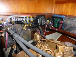
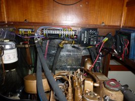
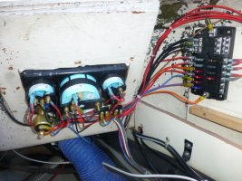
(picture 1 ower terminal strip, Eliminator) [Picture 2:Ground strip on left, power center,] {Picture 3: The fuse block has a cover, the black}
(battery management right) [3 stage regulator, relay] {wire left is a ground for the fish, the grounds
{are at the top of the fuse block}
rest of the system was running on 10.7 volts. This was caused by a bad ground and a stuck glow plug switch. A closer look showed the wrong push switches for the glow plug and start circuits and a Honda starter switch that cannot handle the loads that the glow plugs demanded. The main harness was 15' longer than was necessary. It wrapped back and forth in the cockpit. This meant that the glow plug circuit was 30' longer than was necessary. No wonder the glow plugs dropped the voltage to 10.7 volts. Added to this, various wires were spliced into the harness, some fused, some leading to nowhere. This system? was a fire waiting to happen.
I added a Blue Sea 12 fuse fuse block near the panel with a grounding bar. Terminal bars were put high in the engine compartment for the power distribution and grounds. A relay was added for the glow plugs. Only one main ground now goes to he engine.
On the day of the test, it was twenty nine degrees out and the engine block was in the high thirties. The engine started in two turns of the starter after 15 seconds of glow plugs. The voltage drop is now to 12.1 volts with the plugs on.
The wiring seems to be a total success. I attempted to attach a couple of pictures. hopefully they came through.
Bob Morrison
Terra Nova E-34
The descriptions for the three pictures were done over the top of each picture. The program is jumbling them together so I attempted to differentiate each one by :
Picture 1 ( )
Picture 2 [ ]
Picture 3 { }
Hope that helps.
(picture 1
ower terminal strip, Eliminator) [Picture 2:Ground strip on left, power center,] {Picture 3: The fuse block has a cover, the black}(battery management right) [3 stage regulator, relay] {wire left is a ground for the fish, the grounds
{are at the top of the fuse block}
Attachments
-
 P1000274.JPG170.5 KB · Views: 114
 -
 P1000273.JPG164 KB · Views: 105
 -
 P1000269.JPG153.5 KB · Views: 125
Last edited: