What's wrong with this electrical plan?

Tooluser

Flǎneur
"There is no desire so universal as the desire to edit someone else's copy, sail trim, or electrical system."

My new E381's electrical system is serviceable, and somewhat upgraded, but a bit heterogenous.
For example, it still has a bow battery for the windlass, but no real charging plan for it. Many cables are undersized, and charging sources are connected to only one battery or another, yielding anxiety for longer cruises. I've designed a new layout and I'd love critique and commentary. It's already begun on my blog post (thanks @Nick J !) so I wanted to move it here before it grew too much over on the blogs! I'd love to hear what you've done with your 40-year-old electrical system and what you wish you had.

Design Goals:
- Any charge source will charge all batteries
- Reasonable State-of-Charge readout available for house bank
- Emergency backup ability, but otherwise automated

The original design:
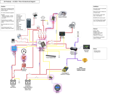
S:V Island Bird Original Electrical Diagram.png
You can see the multiple chargers, ability of the alternator to charge only the start battery (which doesn't seem much usage, since it only starts a small diesel, thus wasting the existence of the alternator and flat PNW days), and the dizzying multiple-1/2/B switches I still don't understand.

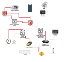
Below I've removed the windlass battery and replaced it with two large 2AWG cables to the forepeak. The starter battery now charges from the house bank via a DC-DC charger - here it shows as an ACR, but I'll actually use a Victron Orion, I think. I've added a battery monitor and missing switches.

My open questions I'd love your thoughts on:
- Is anyone going to talk me into keeping the bow battery for the windlass?
- I could get Magnum's battery monitor, which integrates with their remote, or add a Victron. Victron would be another 'box', but they have a reputation for being much more open-source and flexible. (And a hassle to get support from. . . . any Victron owners?)
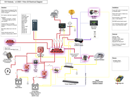

S:V Nobody Wiring Diagram v4.png
 

Christian Williams

E381 - Los Angeles
Senior Moderator
Blogs Author
General note: the Forums are expressly for discussions like this one. The Blogs are not designed for Q & A, or useful argument, but are more for reports of completed projects and write-ups of adventures without the expectation of searchable commentary.

The distinction may not be obvious, but is important in keeping information together in a searchable form. Which is why resurrecting old forum titles is so admired when possible, rather than starting a new thread on a popular topic. Forum=discussion, Blog=report.
 

AlanO

Member II
Joshua-

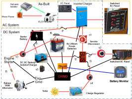
I think you are on the right track with your conceptual plan. I did the refit of our 1988 38-200 last winter. I revised the conceptual plan 4 times before implementing and it changed again during the build. The following is the as-built. We've had Gravlax for about a year and half and this was the first big unanticipated refit project. The purchase survey identified a number of issues that needed attention and during a stress test before our first cruise I determined the two 8D lead-acid house batteries were shot which prompted a refit rather than simply fixing the surveyor-identified issues. One of the 8D batteries was under the V-berth, and I wanted it and the 30 feet of cable out of there!

We have a manual windlass that I would like to replace with an electric. I'm considering whether to put a small 24V battery up there for the windlass. My thinking is a 24V windlass system requires a much smaller cable, but it will require a separate DC-DC charger. Assuming your windlass is 12V, the concern might be the voltage dropoff for a long cable run, if you pull the forward battery.

My retirement cruising plans include significant off-grid areas, so I went with a higher-cost refit that included Lithium house batteries. That said, your choice of AGMs is fine. I decided the high upfront cost would eventually be offset by their longevity (3,000 charge cycles) and the charging profile, acceptable depth of discharge (80-90%), and smaller size and weight were nice features. Fortunately, the POs had installed a new 100 Amp alternator that is up to the high output needed for rapidly charging lithium batteries. I'm not familiar with the components you have in your diagram. I went with the Victron 1200W Inverter/Charger, battery monitor, DC-DC charger, and solar charge controller. In part, because they were bundled by the battery manufacturer which was also a Victron vendor, so I was confident they would work together. The battery manufacturer I used, Dakota Lithium, is based in Seattle and have technical expertise in-house with the Victron products. I had a problem with the Inverter/charger, took it to their warehouse and they swapped it out on the spot. The inverter is a luxury item for sure, but the countertop ice-maker seems to be real winner with our guests! I have found I really like the Bluetooth integration and apps on my smart phone for monitoring the devices.

Here's a few things to consider:

1) Don't forget the new tools you may need. Cable-cutter, terminal crimper(s) for large and small wires, heat gun for shrink wrap, strippers for large and small wire, electrical fish tape. I had some of this stuff, but needed to upgrade some as well. I bought a hydraulic crimper for the large cable terminals....it was worth it.

2) Try to estimate your cable and wire lengths and terminals ahead of time and buy in bulk. I was only partially successful in doing this. Turned out the cable runs were always a little bit longer than I originally conceived. Because of the cable runs to switches, you will use more red positive cable than black negative cable. The cable terminals were especially hard to estimate because of the different sized cables and that it turned out there was little consistency for lug sizes. The batteries, chargers, BUSes, and switches were often different. I ended up making way too many trips to West Marine for more cable terminals of a different size than I had on hand. There is a definite convenience charge for buying a small number at WM.

3) The biggest frustration I had was pulling old cable and running new cable. Previous installations had an (over) abundance of cable clamps screwed into inaccessible locations. Those were cursing rather than cruising days.

4) Gravlax had neither an Galvanic Isolator or ELCI breaker. My understanding is both are good additions.

5) Pacific Yacht Systems https://www.pysystems.ca/ is a great source of information. Look at their channel on YouTube as well as the website. That is where I learned about switched and unswitched loads and modified my system accordingly.

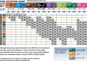
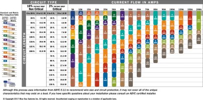
6) Attached are two charts I found useful for selecting cable/wire size and fuses.

7) I hired an electrician to look over my existing system and design plan, then had him back to review my work.

8) My understanding is the one cable that shouldn't be fused is from the starter battery to the starter.

9) The refit will take longer than you think to complete.

Good luck on the refit!

1699052684934.png
 

Attachments

  • As_Built_Design.pdf
    1.4 MB · Views: 6
  • Choose_the_Fuse_Amperage.jpg
    Choose_the_Fuse_Amperage.jpg
    330.7 KB · Views: 4
  • DC_wire_selection_chartlg.jpg
    DC_wire_selection_chartlg.jpg
    361.4 KB · Views: 5

Marlin Prowell

E34 - Bellingham, WA
I agree with your design goals and rewired our boat accordingly. I took out the Off/1/2/All battery switch and replaced with a Blue Seas e-Series Dual Circuit Plus™ Battery Switch (5511e). This is functionally equivalent to the three battery switches in your new design, but in just one physical battery switch.

I don’t think your unswitched circuits are wired correctly. There should not be any switches between the battery and these circuits; it should be impossible to remove power from the unswitched circuits. Pacific Yacht Systems has a lot of good information on marine electronics. Here is their diagram for wiring switched and unswitched DC circuits.

I added fuses to all the circuits, most of which had not been fused. I used a Blue Sea SafetyHub 150 Fuse Block for the unswitched house battery circuits and used these Eaton modular fuse blocks to make compact custom fuse blocks for the engine battery and switched house battery circuits. Check the data sheets to see how to construct your own fuse blocks.
 

Tooluser

Flǎneur
This is functionally equivalent to the three battery switches in your new design, but in just one physical battery switch.
Correct me, but isn't this distinct in one way: It is impossible to turn off one bank while turning on another. Both are either on, or off, with this switch?

That is, it is impossible to turn on 2 and off 1.

I don’t think your unswitched circuits are wired correctly. There should not be any switches between the battery and these circuits; it should be impossible to remove power from the unswitched circuits.

This is a really good point; thank you. I need to think about this. I thought it desirable to completely disconnect such loads, since it would only be in a very intentional manner. I'll read up on PYS' approach. Thanks.

I note you're using the SafetyHub. I am on the fence there. What made you decide to go with that, rather than a simple hot bus and individual fuses at each device?
 

Tooluser

Flǎneur
My thinking is a 24V windlass system requires a much smaller cable, but it will require a separate DC-DC charger. Assuming your windlass is 12V, the concern might be the voltage dropoff for a long cable run, if you pull the forward battery.
You've got it exactly. To maintain nil loss, that's a couple hundred bucks of 2AWG copper. But a battery costs about the same, and is heavier in the bow, and requires a charger besides. I'm not sure it's a win, and I note that more and more systems don't bother, and just have a fat house bank.
 

Loren Beach

O34 - Portland, OR
Senior Moderator
Blogs Author
One minor point (or perhaps not so minor)... Our surveyor advises us to always have the DC power thru a master switch for an instant disconnect in case of a fire somewhere in the system. That is a great basic feature of the 1-2-all switch. A lot of boats have different devices and circuits that go directly to their battery bank(s), which complicates things a lot.
 

Mr. Scarlett

Member III
The best pactice would be to buy the 2AWG and run it to the house bank.
I use an ACR with a Blue Sea 6011 battery switch (mini version of the one mentioned above.) The ACR draws from both banks until a lower threshold is reached somewhere around 12.5 volts. Then the banks arer isolated from each other leaving the start battery topped up.
Safety Hub 150, SmartPlug and a ProMariner 12-50 charger are other top notch components I use that I know I'll only buy once. Also a Balmar 100AH alternator that we really didn't need. Ours has a generic 12V start and a pair of 6V.
 

Marlin Prowell

E34 - Bellingham, WA
Correct me, but isn't this distinct in one way: It is impossible to turn off one bank while turning on another. Both are either on, or off, with this switch?
That’s correct, but I cannot think of a use case, even an uncommon use case, where I would need that. For me, reducing the complexity by merging three switches into one (instead of remembering how to set them all) is more important.
I note you're using the SafetyHub. I am on the fence there. What made you decide to go with that, rather than a simple hot bus and individual fuses at each device?
I needed both high amperage circuits (battery charger, alternator) and low amperage circuits (battery monitor, electrical panel battery sense) connected to the unswitched house battery circuit, and also a ground bus bar. The SafetyHub provides all those in a rather compact format, and I needed to install this in a smallish space, but it’s just one way to do all this.
 

Marlin Prowell

E34 - Bellingham, WA
One minor point (or perhaps not so minor)... Our surveyor advises us to always have the DC power thru a master switch for an instant disconnect in case of a fire somewhere in the system. That is a great basic feature of the 1-2-all switch. A lot of boats have different devices and circuits that go directly to their battery bank(s), which complicates things a lot.
Nigel Calder describes unswitched circuits in Boatowner’s Mechanical and Electrical Manual, Fourth Edition on page 242 in a section titled Circuits that bypass the isolation switch. He doesn’t use the term “unswitched circuits”, but that is what he describes. He uses unswitched circuits for the charging devices and the bilge pump. I have done the same. It is impossible to power off the bilge pump in our boat without pulling a fuse out a fuse holder. No grandkids fiddling with the switches on the electrical panel can inadvertently turn off the bilge pump.

It is important to note that he says that every circuit, switched or unswitched, must have a fuse. Adding fuses to all circuits was one of my primary objectives when rewiring a few years ago. There were a number of circuits that were not fused, including the main feed from the house battery to the electrical panel on the other side of the boat, and these were all potential fire hazards.

With older boats that do not meet today’s fusing standards, a OFF/1/2/ALL battery switch is a good plan B. But if there is a fire, you need to be present at the boat, recognize the problem, and be able to get to the battery switch to turn it off. In my opinion, fusing everything is a better option because the fuse will blow and interrupt the circuit before the shorted out wire has a chance to catch fire.
 

ConchyDug

Member III
If you're hitting the life expectancy of the AGMs I'd dump them and go lithium. It's more expensive up front for the infrastructure but lithium batteries are almost the same price as good AGMs now. Plus the wiring in a 40yr old boat is probably due for replacement. I just dropped 400ah of lithium in my 38 along with a 3k inverter/charger. That 400ah weighs 80lbs(20lbs each) compared to one 90ah AGM weighing 80lbs with roughly 45ah useable. I use DC to DC chargers to charge the house bank via the lead starter battery. You can charge the lithium direct with the alternator someway but I liked the DC charger method more when doing research. I got rid of the 1/2/both switch and have separate systems with just on/off service disconnects. With the new house bank I can run the 16k BTU air conditioner for 2hrs, that would take crap load of lead acid.

Victron makes great stuff their ecosystem of products works great together and is super intuitive. I monitor it all with the same tablet I mirror my plotter with. If you're buying all new for the project I'd go with victron on major components. I used bits and pieces of victron wiring diagrams when developing my system. They have several with anchor windlass diagram examples from what I remember.


When buying wire Ancor prices on Amazon are hard to beat. I bought probably $1500 worth of wire on there which would've been closer to $2500 at the local boat supply shop, I even have access to a Port Supply card via my wife and Amazon was still cheaper.
 

Tooluser

Flǎneur
That’s correct, but I cannot think of a use case, even an uncommon use case, where I would need that. For me, reducing the complexity by merging three switches into one (instead of remembering how to set them all) is more important.
The case would be where a totally dead battery cripples those critical loads.

It seems to me there are a few design goals for a system like this - or, a few failure modes meant to be addressed.

Those modes are:

- One bank is 'normal dead' ie 11v
- One bank is totally discharged
- catastrophic failure of the battery/safety

In the event of a 'normal dead' (say 'mostly dead') battery, combining both banks is totally fine. It will enable all those loads, including the critical ones, to function.

In the event that one bank is totally discharged, combining the two can render both inoperative as the truly dead battery sags the functional one. In such a case, and in the third case, being able to completely isolate each battery means that those loads you think of as enormously important '24 hour' loads can be switched to the other battery, by removing the dead battery from the system entirely while still powering all loads.

Now when are these failure modes likely to arise? In the event of a sudden failure (eg, the lockout that lithium batteries are susceptible to), you want immediate power availability. In the event of a 'soft failure', there is no emergency, but you still want to resurrect those loads.

The first failure mode is probably more common than the second, and has a shorter response window. As such, it's probably the mode to ensure you can deal with. This is probably the rationale that leads to putting 'unswitched' loads before the battery disconnect.

However, the second/third modes are real, and a fast response to them can be valuable too. The negative consequence (aside from people thumping you with Calder's heavy book) of putting unswitched loads after the battery disconnect is that you have introduced one more point of failure - the switch itself.

The argument can be made that this is not a significant risk for the benefits, namely, being able to resurrect these priority loads trivially by flipping a few switches, versus actually moving cables (the other recovery path, if switches don't suffice).

Some find managing three switches needlessly complex, or worry about children or others flipping switches. They have a clear path to follow.

Blue Seas implicitly goes with position 1 - 'some loads before a switch' - in their documentation for their safety bus showing what to connect in each of the two optional positions. (They would say, buy two buses!) Calder, too.

I had sworn that PYS had materials saying the opposite, but the link you share is in the same camp. It's puzzling. What is their response to this case where a totally dead battery cripples critical loads, do you know?

fusing everything is a better option

I agree; I'd even say fusing everything is absolutely required. If you're modifying an electrical system and you haven't finished fusing everything, do that first, and then come back and do whatever you thought was a higher priority.
 
Last edited:

Loren Beach

O34 - Portland, OR
Senior Moderator
Blogs Author
Fusing everything is absolutely required. If you're modifying an electrical system and you haven't finished fusing everything, do that first, and then come back and do whatever you thought was a higher priority.
I Agree.
I do not have the citations from the ABYC manual to quote, but our surveyor always wants all circuits fused/breakered within X inches of each battery terminal. Or easily switched.
The thing is, if you cannot meet the "advisory" standards of the ABYC, your boat will not pass a survey, and furthermore either be uninsurable or subject to the insurer refusing to pay in case of a loss traced to your boat's improper DC system protections.

We do have a (very) few circuits wired directly, but to a Blue Seas fused terminal mounted on the pos. terminal of the battery.
That's why we value our Very Basic 1-2-all switch. IIRC the average time we have to control/extinguish an electrical fire is maybe a minute. Max. This is generally fewer minutes/seconds than the average flooding emergency that might result from a split hose or similar.
 

Tooluser

Flǎneur
Here's the shortest summary I found of PYS' take -

You should have an unswitched positive distribution for each battery bank (for instance battery chargers, solar controllers, bilge pumps, are connected here). In turn each battery bank can also be connected to a single common positive switched distribution. Effectively that gives you 3 positive distribution: 2 unswitched distribution (one for each battery bank) and 1 switched distribution that is connected to both unswitched distribution via battery switches.

He doesn't explicitly address crippling critical loads with a dead battery that can't be cut out of the system.


Now I'm a bit flummoxed. I wanted to be able to redirect those chargers, windlass, etc to a valid bank in the event of a crippled battery. I guess the answer becomes "do it by moving the cables, in that rare case".
 

Tooluser

Flǎneur
@Marlin Prowell your comments have thrown me for a loop. I redesigned this to have no switches before the bus and to mimic the Blue Seas diagrams. . . and I'm finding no need for a battery switch at all. My panel is switched, and all the other loads:

- eg windlass has their own switches
- eg bilge pumps are unswitched
- sources - eg solar, alternator - go directly to the 'battery'.

I end up putting a combiner between the panel and the safety bus, for emergency starting or load management, and that's it. This seems like it can't possibly be right!

Thanks for stirring me up so much.

Here's a new version. It has the following changes:
  1. Blue Seas Hub is before any battery switch (DC Panel is already switched w/ its own breaker). Nothing else 'needs' switches (see above)
  2. I realized my existing TrueCharge 40 was worth keeping, and re-added it. The Magnum is now inverter-only. This is as-built on the boat currently.
  3. I added a lightweight Victron Orion charger. It's small; 9A. But I think this is fine for charging a start battery. Could go to a 20.
  4. I replaced the Magnum BM with a Victron monitor.
I probably should add a dedicated inverter switch.
There's a starter switch so the starter can be disabled independently of combining batteries.

S:V Nobody Wiring Diagram v5.png
 

Nick J

Sustaining Member
Moderator
Blogs Author
Joshua,

Here's a few more comments and suggestions for your current design

  • Battery Switch – I really like the idea of being able to switch a battery completely out of a circuit, so I would keep the switch (just a simple on/off style) on the house bank. On our last trip, I had a loose cable going to our start bank and I didn’t realize it for a while later. Having the battery switch and combiner allowed me to turn the start battery completely off and start my motor using the house bank. Once we were underway, I had my wife take the helm while I troubleshot the start battery. The switch configuration allowed me to do everything with the battery out of the system. Once the lug was tightened to the battery terminal, I switched on the start battery and turned the combiner off. My alternator was happy, I was safe, and I didn’t have to move battery cables.
  • House Battery type – If you already have the WM AGM batteries, keep them and save some cash for all the other projects. But…if you are looking to purchase new batteries, here’s a quick cost comparison between West Marine 190 ah in a 2X2 configuration and a Dakota LiFePO4 200ah bank (taken from WM and Dakota battery web sites):
WM 190ah AGM (4x6vdc)Dakota LiFePO4 200ahDakota LiFePO4 400ah
Cost​
$2,019.96​
$950.00​
$1,900.00​
Weight​
280​
59 Lbs.​
118 Lbs.​
Stated AH​
380​
200​
400​
Usable AH %​
0.5​
0.9​
0.9​
Usable AH​
190​
180​
360​
Physical size (in^2)​
3210.24​
1659.0828​
3318.1656​
Life Span (cycles)​
300​
3000​
3000​
Warranty​
1.5yrs​
11yrs​
11 yrs​
Cost over 3k Cycle​
$20,199.60​
$950.00​
$1,900.00​


This is obviously best-case scenario, but it does a good job of illustrating the advantage just in cost of a LiFePO4 bank. There’re additional benefits including charge time and voltage over the discharge cycle to name a few. If you address the charging requirements by connecting the alternator to the lead acid start battery and using a higher output DC to DC charger, the overall cost of install is in the ballpark of reasonable.

  • Inverter Chargers – They’re great in some situations, but I don’t think boats are one of them unless the inverter can handle 100% of the AC loads on a boat. Anything les and you end up having to make the install more complicated than it needs to be with additional sub pannels. The main problem is inverters are ideally wired after the main battery switch and chargers should be before, but inverter chargers only have a single connection to the DC bus. If you haven’t already purchased the Magnum 1212, I would look for an independent inverter. If you already own the device, is it possible to disable the charge function and let the True Charge handle shore power charging?
  • Tapped connections – tapped connections like where you have the DC to the TrueChare 40, DC to DC charger and AC to the Magnum are easy to do on a diagram, but require more hardware in the real world. Tapped connection needs to happen at a terminal (please don’t do this on the battery terminal), bus, breaker or fuse panel. It sounds simple, but it’s one item that gets a lot of people when they’re doing their own install and if you don’t think it out ahead of time it can easily turn a good idea into a mess in the real world. This is one of the reasons I really like the Blue Seas Safety hub. It’s a bus and fuse block all in one. I would install a second safety hub on the starter battery (they make a smaller version to save cost and space) then run all of your non switched high load circuits to the MIDI/AMI terminals (alternator, charger, DC to DC, main house load feed etc) and the lower load circuits to the ATO/ATC fuses.
  • Fuse / breaker size – Size the cable to account for your accepted voltage drop (3-5% is ideal), then size your breaker or fuse to protect the cable. Don’t worry about the device in the end of the circuit unless the devise specifically calls for it. If it does, there’s usually a second protection device located closer to the devise (stereos, windlass, and navigation electronics is a good example of this). This will ensure your circuits are fed with adequate power, your wiring is protected, and you’re avoiding false trips.
  • Grounding and bonding – It’s good practice to bring all negative wires to a dedicated negative bus then have a single connection from there to the boats ground (engine block). Don’t rely on the block to provide a negative connection. You can argue that a giant hunk of iron is a damn good bus, but a proper tin coated piece of copper with dedicated terminal posts is even better. If you lose the connection to the block, you won’t loose the start battery. It also removes the mess of grounds that’s typically found on a starter negative connection or bell housing bolt. Engines vibrate, dedicated buses don’t.
Attached is a really basic drawing of what I’m working towards. I’ve left a lot out for clarity, but it’s a good representation of the general connections:
 

Attachments

  • Boat Elec Overview.pdf
    1.3 MB · Views: 9

Tooluser

Flǎneur
Battery Switch – I really like the idea of being able to switch a battery completely out of a circuit, so I would keep the switch (just a simple on/off style) on the house bank.
Thank you for saying this. I'm coming to the same conclusion! I don't think the switch is a failure mode worth worrying about, relative to its benefit.

If you already have the WM AGM batteries,
I do, but if they go, I will make the switch to LiFePo, most likely.

If you haven’t already purchased the Magnum 1212, I would look for an independent inverter. If you already own the device, is it possible to disable the charge function and let the True Charge handle shore power charging?
That’s exactly what I’ve done! I love this!

If you look at the second version of the diagram, I have above, you should see that annotation. (Also, anything with the purple glow is new; everything else is adapted from what's present.) The TrueCharge and the Magnum are both on the boat already. I realized I should stick with the TrueCharge for the charging as it has a much better capacity. The Magnum will do for now; it’s a very small inverter, and I will probably replace it eventually.

This is one of the reasons I really like the Blue Seas Safety hub

I am excited to say my second version seems to be pretty much in line with the things you are suggesting, I think. The biggest difference I see from your diagram (thank you for it) is that I have the alternator charging the main house bank rather than the starter battery. This seems a bit unusual, historically, but seems to be increasingly normal. Can you think of any reason not to? I could instead charge the starter, but then I'd need a larger capacity DC-DC charger.

I couldn’t see a reason to limit the charge rate of the house bank to whatever the Orion DC DC charger could do, so I plan on all the charging going directly to the house bank, and then a small DC-DC charger should be plenty. I should have enough room on the BlueSeas hub to, as you say, have the high-amp stuff on AMI fuses and the rest on the ATCs.

Because of that, as far as I can tell, it ends up not needing a BlueSeas bus on the start battery really - the charger should go through the switch, and that should do it. But I can always put on a small one.

(And thank you for the suggestion about the ground; noted.)

What do you think?
 

Nick J

Sustaining Member
Moderator
Blogs Author
I decided to have the alternator charge the starting bank then use a DC to DC converter to charge the house because I was looking for an inexpensive way to protect my alternator from the BMS shutting off the LiFePO4. Having a LA battery first gives me some cushion. There's other methods of protecting the alternator but they all come at a cost. The disadvantage to my setup is the limited charging through the DC to DC charger (50 amps in my case). So far it works well for me, but in your case with AGMs, I think you're right to connect the alternator directly to your house bank.

The safety hubs really helps those tapped or branched connections. Otherwise you would have to build jumpers, busses or a combination of both which takes up more room. It also allows you to more easily break up non switched circuits without stacking lugs on the battery. There's always connections you forget (radio memory, voltage meter, battery monitor etc. For some extra redundancy, I ran the main bilge pump off the starter bank and the shower bilge pump off the house bank. Since there's a limber hole high up between the two, if one fails, the water will just spill over and be pumped overboard by the working pump. It's never fun to need one more circuit and not have an existing place to land it. Planning now will pay off in the future when the time comes to add an additional circuit (same applies to breaker panel sizing).

If you're looking to save a little cash, you may be able to forgo the terminal mounted fuse if you can mount the safety hub within 7" of the battery terminal. This would also remove and additional fuse type which helps with your spare inventory. Minor factor, but it's one of those little things that just makes life easier when you out and about.

Keep the ideas coming, you're on the right track it's all about refining now so you limit head scratching during the install and frustration in the future.
 

Tooluser

Flǎneur
I decided to have the alternator charge the starting bank then use a DC to DC converter to charge the house because I was looking for an inexpensive way to protect my alternator from the BMS shutting off the LiFePO4.

I dig it. Thanks for the corroboration.

The safety hubs really helps those tapped or branched connections. Otherwise you would have to build jumpers, busses or a combination of both which takes up more room. It also allows you to more easily break up non switched circuits without stacking lugs on the battery. There's always connections you forget (radio memory, voltage meter, battery monitor etc.

You're right, of course.

For some extra redundancy, I ran the main bilge pump off the starter bank and the shower bilge pump off the house bank. Since there's a limber hole high up between the two, if one fails, the water will just spill over and be pumped overboard by the working pump.

I was thinking the same thing. I don't actually know if the E38 has a limber hole between the main and secondary bilges, but I have assumed it does, since to fail to do so would seem unreasonable. But I imagine Mr @Christian Williams would know for certain?

Keep the ideas coming, you're on the right track it's all about refining now so you limit head scratching during the install and frustration in the future.

Oh yes. As we used to say, "a couple of months in the laboratory can save hours in the library".
 

Vtonian

E38 - Vashon
I'm still doing forensics on my wiring but FWIW, for my windlass the PO used a separate, relatively light 100AH Lithium battery in the V berth, connected to a charger plugged into an AC outlet. Instinctively, I don't like it but OTOH, it works, it saves running big cables forward, and covers the different task of charging Lithium (the other batteries are all AGM). I haven't decided whether it's a Rube Goldberg special or just unsightly but elegant simplicity.
 
Top