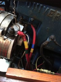
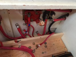
So the first thing to do was trace the wires and figure out what was what. Since MOST of the cable was good Ancor marine wire, my plan was to re-use it, and re-terminate it, using the FTZ power lug crimping tool as found on Marine How To. I did this by using electrical tape, then when I was done, things were re-labeled in a more permanent way using a P-touch labeler and some clear heat shrink tubing. You can see my color coding at the alternator, and in the box during the process.
Next was to figure out what our new electrical system was going to be like. I made up a new diagram:
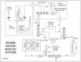
This new layout does a few things. It creates a charging circuit, which was beneficial when adding the solar (separate blog coming soon), and means that if you turn the engine over, even if your 1/2/B switch is in the wrong place, the alternator always has a place to send charging. This second change necessitates a master house bank switch so you can truly isolate the DC system, but that was ok for me. Also, the engine battery is charged by both the engine when running, but also is kept topped up by solar.
One disadvantage to using the ACR over a DC-DC charger is that I am running all charging sources set for the AGM batteries, which means the FLA starting battery isn't seeing the voltage it should. I decided this was a minor niggle for me, and it means I don't have to figure out where to put a DC-DC charger, which is much larger than the ACR. I do plan on replacing the FLA with a AGM battery when it fails, so then it will good to go.
Another benefit to this vs the old setup is I have wired the batteries for equal charging and use. By taking the positive off of one battery, and the negative off the battery at the opposite end, the current must go through all batteries.
Once this was done, I started laying out the battery box. I couldn't get 3 batteries in there with acid battery boxes, and couldn't find a 3 battery box, so I gave up on acid collection. This is one of the less awesome things but it was a compromise I felt I had to make, and being AGM's, they were very unlikely to vent. I did create a tray to hold the batteries, and elevated it so I could run wires underneath. This creates a much neater box. You can see in the picture below the pieces of wood that create cable channels.
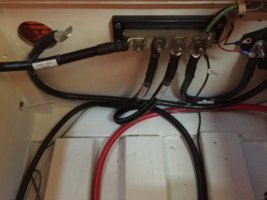
Here is the tray installed before painting for a test fit-up. It does have battery hold downs attached, and it is attached through itself, the risers, and then the floorboards with stainless steel screws, so it isn't going anywhere.
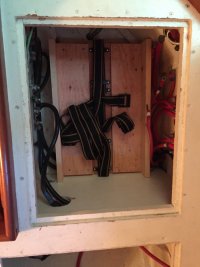
Finally we have the basic layout complete:
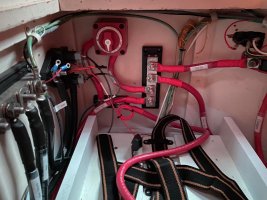
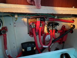
It's a tight fit, but the batteries are now snug, and all the cables are tidy!


Next was to figure out what our new electrical system was going to be like. I made up a new diagram:

This new layout does a few things. It creates a charging circuit, which was beneficial when adding the solar (separate blog coming soon), and means that if you turn the engine over, even if your 1/2/B switch is in the wrong place, the alternator always has a place to send charging. This second change necessitates a master house bank switch so you can truly isolate the DC system, but that was ok for me. Also, the engine battery is charged by both the engine when running, but also is kept topped up by solar.
One disadvantage to using the ACR over a DC-DC charger is that I am running all charging sources set for the AGM batteries, which means the FLA starting battery isn't seeing the voltage it should. I decided this was a minor niggle for me, and it means I don't have to figure out where to put a DC-DC charger, which is much larger than the ACR. I do plan on replacing the FLA with a AGM battery when it fails, so then it will good to go.
Another benefit to this vs the old setup is I have wired the batteries for equal charging and use. By taking the positive off of one battery, and the negative off the battery at the opposite end, the current must go through all batteries.
Once this was done, I started laying out the battery box. I couldn't get 3 batteries in there with acid battery boxes, and couldn't find a 3 battery box, so I gave up on acid collection. This is one of the less awesome things but it was a compromise I felt I had to make, and being AGM's, they were very unlikely to vent. I did create a tray to hold the batteries, and elevated it so I could run wires underneath. This creates a much neater box. You can see in the picture below the pieces of wood that create cable channels.

Here is the tray installed before painting for a test fit-up. It does have battery hold downs attached, and it is attached through itself, the risers, and then the floorboards with stainless steel screws, so it isn't going anywhere.

Finally we have the basic layout complete:


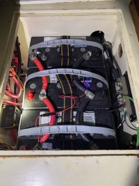
It's a tight fit, but the batteries are now snug, and all the cables are tidy!

