It was clear when we bought the boat that it had been designed to sit at a dock with the shore power charger doing the bulk of the work. Then when offshore, I assume it was all about the 100A alternator. However, we weren't going to be having our boat at a dock, so it was imperative that we got some solar onboard, and hopefully enough to cover most of our needs.
We chose to have two 100 Watt panels on our Bimini. These are semi-flexible, and it took quite a bit of time and money, but finally we got the local canvas place to sew pockets on for us. We really like how they don't show at all if you are looking at the boat from the side.
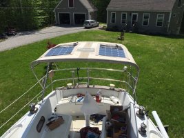
I wired the two panels in parallel because there was a large possibility of boom shading, so that was going to be the best approach. However, one of the downsides was I had to run large wires, because the amps were low, so losses were critical. I bought some special 2 into 1 heat shrink connectors that allowed me to crimp a single 10 gauge wire on one side, and two 10's on the other.
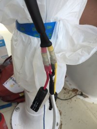
This gave us our parallel setup. And by careful measuring, it puts the connectors in just the right places to hide in the bimini zipper area.
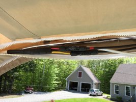
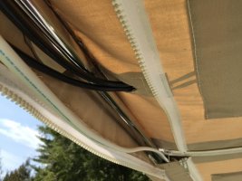
When closed, you can't see any of this! Then we ran the wire down the bimini and went into the boat through a scanstrut gland
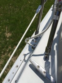
Once inside the boat, it goes to a Victron MPPT controller, which was oversized for future expansion.
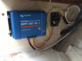
You aren't supposed to disconnect the solar connectors under load, so the breaker next to the controller lets me break the circuit before I unplug them, and protects the controller and wire.
Finally here is where it all comes together into our "charging circuit".
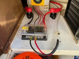
You can see the bottom of the shore power charger and the wires from the solar are coming up on the right and to the fuse block. This all gets sent to those two posts, which change from the 8 gauge wire that will fit the fuse block, to a 2 gauge wire to minimize losses headed back to the battery bank. The solar controller is also linked by bluetooth to a voltage monitor that can be seen on the top of the batteries below (under the middle handle, small square, two wires), which compensates for voltage drop and temperature. Since this is our main source of charging, it was important that it be as correct as possible.
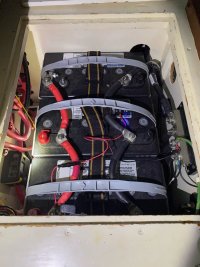
So far this has been an awesome setup. We come to the boat always with a full charge, the batteries are happy, and most days we can sail without ever needing to charge with our engine, even running the fridge!
We chose to have two 100 Watt panels on our Bimini. These are semi-flexible, and it took quite a bit of time and money, but finally we got the local canvas place to sew pockets on for us. We really like how they don't show at all if you are looking at the boat from the side.

I wired the two panels in parallel because there was a large possibility of boom shading, so that was going to be the best approach. However, one of the downsides was I had to run large wires, because the amps were low, so losses were critical. I bought some special 2 into 1 heat shrink connectors that allowed me to crimp a single 10 gauge wire on one side, and two 10's on the other.

This gave us our parallel setup. And by careful measuring, it puts the connectors in just the right places to hide in the bimini zipper area.


When closed, you can't see any of this! Then we ran the wire down the bimini and went into the boat through a scanstrut gland

Once inside the boat, it goes to a Victron MPPT controller, which was oversized for future expansion.

You aren't supposed to disconnect the solar connectors under load, so the breaker next to the controller lets me break the circuit before I unplug them, and protects the controller and wire.
Finally here is where it all comes together into our "charging circuit".

You can see the bottom of the shore power charger and the wires from the solar are coming up on the right and to the fuse block. This all gets sent to those two posts, which change from the 8 gauge wire that will fit the fuse block, to a 2 gauge wire to minimize losses headed back to the battery bank. The solar controller is also linked by bluetooth to a voltage monitor that can be seen on the top of the batteries below (under the middle handle, small square, two wires), which compensates for voltage drop and temperature. Since this is our main source of charging, it was important that it be as correct as possible.

So far this has been an awesome setup. We come to the boat always with a full charge, the batteries are happy, and most days we can sail without ever needing to charge with our engine, even running the fridge!
