Bilge Pump Wiring

Eric Gordon

1975 E27 - Sea Star, Yanmar 3GM30F Dana Point, Ca.
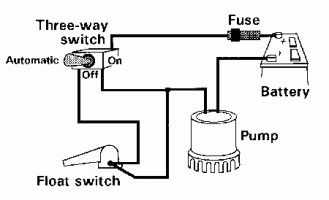
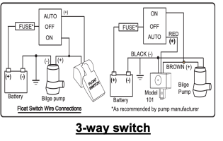
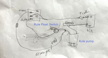
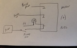
So, the “switch” which activates the pump is merely placed on the positive side of the circuit like this diagram, correct? Thus, it opens the circuit, or closes it, but only if the switch is in the automatic position?

The negative is direct to the equipment, and is never involved in any of the wiring other than that? Does this mean that only positive wires are involved in switches and fuses? (Forgive my electronic ignorance).
 

Attachments

  • Bilge_Wiring1-1959881456.gif
    Bilge_Wiring1-1959881456.gif
    3.4 KB · Views: 10
Last edited:

Kenneth K

1985 32-3, Puget Sound
Blogs Author
So, the “switch” which activates the pump is merely placed on the positive side of the circuit like this diagram, correct? Thus, it opens the circuit, or closes it, but only if the switch is in the automatic position?
Yes. Except that it is a 3-way switch, so it provides two paths to close the circuit. In "auto," a second switch (the float switch) must also be closed before the circuit powers the pump. In "manual," the circuit becomes closed (and the pump powered) as soon as the switch is placed to manual.

The negative is direct to the equipment, and is never involved in any of the wiring other than that? Does this mean that only positive wires are involved in switches and fuses? (Forgive my electronic ignorance).
That is typically how things are wired, but only from the standpoint of safety. All of the switches could also be wired in the negative side of the circuit--the user wouldn't see any difference in how the circuit operates if this were done, but this can be dangerous.

The diagram you show is safer. Fuses and switches are usually placed as close to the positive source as possible so that when they are switched off (or, blown in the case of a fuse), everything after the switch/fuse is no longer a "hot" wire. If switches/fuses are placed in the negative side of the circuit, all the wiring from the (+) source up to the switch/fuse will ALWAYS be "hot." The latter is dangerous because it leaves a much longer length of "always hot" wire. This is why fuses are placed as close to the battery as possible, and switches are place in the (+) side of the circuit.
 
Last edited:

Christian Williams

E381 - Los Angeles
Senior Moderator
Blogs Author
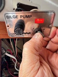
Tell Ken what brand model three-way switch you have, what pump, and if youhve an external float device such as Water witch.

At the time I found the wiring of these components quite beyond my own intuition, even though the install diagrams are available.
 

Eric Gordon

1975 E27 - Sea Star, Yanmar 3GM30F Dana Point, Ca.
Tell Ken what brand model three-way switch you have, what pump, and if youhve an external float device such as Water witch.

At the time I found the wiring of these components quite beyond my own intuition, even though the install diagrams are available.
OK, will do. Yes, I’ve looked at literally scores of diagrams, and all they seem to do is raise more questions. I just took delivery of the Mech and Electrical Manual (Nigel Calder), so I am sure that will help my understanding. The internet is fine, but there’s nothing like a hardback manual.
 

Eric Gordon

1975 E27 - Sea Star, Yanmar 3GM30F Dana Point, Ca.
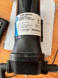
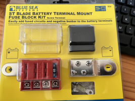
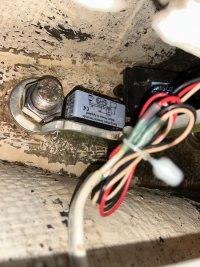
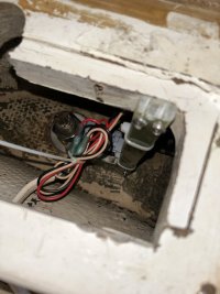
Here’s the equipment I’m installing;

- JABSCO PAR-MAX 4 Bilge Pump (12v)
- Water Witch model 101 (still awaiting delivery)
- Rule Bilge Pump Switch
- Blue Sea Systems Terminal Mount

(see pics)


PS- I intend to attach only two pieces of gear directly to the house battery; the bilge pump and the VHF.
 

Attachments

  • IMG_4392.jpeg
    IMG_4392.jpeg
    135 KB · Views: 7
  • IMG_4407.jpeg
    IMG_4407.jpeg
    117.4 KB · Views: 7
  • tempImageT1A13s.png
    tempImageT1A13s.png
    1.7 MB · Views: 8

bigd14

Contributing Partner
Blogs Author
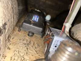
Make sure you mount the Water Witch at the appropriate height.


I used a L-shaped scrap of G10 tapped to accept the mounting bolts to hold the Water Witch slightly off the bottom of the bilge. You might need a much longer one to reach the 27’s deep keel sump but the principle is the same.
1729473481211.jpeg

1729473527030.jpeg
1729473700018.jpeg
 

Eric Gordon

1975 E27 - Sea Star, Yanmar 3GM30F Dana Point, Ca.
Thank you. Very informative/helpful.

The batteries I have are West Marine Group 31 Dual-Purpose AGM Battery, 105 Amp Hours
and I see from the package, the Blue Sea battery terminal bus bar says it has a “Continuous Rating” of 100A DC. Is this something I should be concerned about?

Also, I think I’m going to hook up the old “float switch” temporarily tomorrow, since the Water Witch is not coming for a couple of days….

The diagrams on Water Witch were helpful in this regard.
 

Attachments

  • Screen Shot 2024-10-20 at 7.16.46 PM.png
    Screen Shot 2024-10-20 at 7.16.46 PM.png
    103.4 KB · Views: 6

Eric Gordon

1975 E27 - Sea Star, Yanmar 3GM30F Dana Point, Ca.
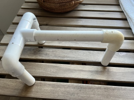
Apropos this project, and not wanting to spend another cent on it, I fashioned, or rather 'Frankensteined,' a stand for the soon-to-arrive Water Witch. It will sit in the rather deep sump on my E27, and I think this should work, plus I don’t have to drill anything into the boat...
 

Attachments

  • tempImageMMQfII.png
    tempImageMMQfII.png
    1.6 MB · Views: 4

Prairie Schooner

Jeff & Donna, E35-3 purchased 7/21
Pilot Light for Bilge Pump Auto Setting?
Eric, I hope you don't mind me piggybacking on your thread for this.
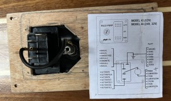
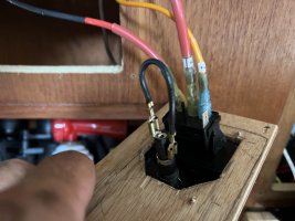
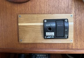
The pilot light for the Rule switch I installed is designed to only light when the pump runs. And this function doesn't work anyway because I didn't want to run an extra wire to the switch for the ground. Otherwise, as wired the system works fine. The switch is mounted in the teak panel aft of the main electrical panel where the PO had a mileage meter. I would like a pilot light to show when the Auto circuit is engaged so as we leave the boat we can do a quick scan to be sure it's on. I bought some 12v LEDs but can't figure out how to add one to this circuit. Can anyone suggest how I can do this?
Thanks,
Jeff

bilge pump_7719 copy.jpeg
bilge pump_7031 sm.JPG
bilge pump_7178 sm.JPG
bilge pump_7067 sm.JPG
 

Kenneth K

1985 32-3, Puget Sound
Blogs Author
I would like a pilot light to show when the Auto circuit is engaged so as we leave the boat we can do a quick scan to be sure it's on. I bought some 12v LEDs but can't figure out how to add one to this circuit. Can anyone suggest how I can do this?
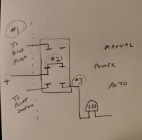
Jeff, I think the easiest way to do what you want is to replace the existing SPDT (single pole, double throw) switch with a DPDT (double pole, double throw) switch. A DPDT switch will have 6 prongs on the back instead of 3. It works just like the switch you have, but it controls two independent circuits with one switch.
IMG_20241021_104337991_HDR~2.jpg

If you can find a DPDT switch that fits, then just:

1. Wire the bilge pump & float switch the same way they are now, to one side of the switch.
2. Wire a bridge across the first and second positive (center) terminals.
3. Wire your LED to the AUTO terminal on the second side of the switch.
 

Eric Gordon

1975 E27 - Sea Star, Yanmar 3GM30F Dana Point, Ca.
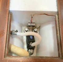
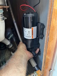
This may seem like a silly question at this point, but I’m wondering if it’s safe/better to mount this bilge pump (see photo) on the interior bulkhead of the galley, which is underneath the sink… As you can see from one of the pictures, the bilge pump would be located in the bilge and could, in the worst case scenario, be covered in water… shouldn’t I only put hoses down there? I guess the question is is can the pump be mounted vertically? See photo.
 

Attachments

  • IMG_4412.jpeg
    IMG_4412.jpeg
    178.5 KB · Views: 6
  • IMG_4415.jpeg
    IMG_4415.jpeg
    121.5 KB · Views: 6

Loren Beach

O34 - Portland, OR
Senior Moderator
Blogs Author
You could email or call the vendor, but I kinda doubt that the mounting positions matters. Any instruction on the box or on a paper in the box?
 

Eric Gordon

1975 E27 - Sea Star, Yanmar 3GM30F Dana Point, Ca.
No it is used from Minney’s. It looks fairly new, no corrosion etc. I think I’ll go ahead and mount it on the bulkhead. Once I get the water witch hopefully the length of wire that comes with it is sufficient. If not, I’ll have to do some splicing . Thanks for your assistance
 
Last edited:

Prairie Schooner

Jeff & Donna, E35-3 purchased 7/21
Jeff, I think the easiest way to do what you want is to replace the existing SPDT (single pole, double throw) switch with a DPDT (double pole, double throw) switch. A DPDT switch will have 6 prongs on the back instead of 3. It works just like the switch you have, but it controls two independent circuits with one switch.
View attachment 51273

If you can find a DPDT switch that fits, then just:

1. Wire the bilge pump & float switch the same way they are now, to one side of the switch.
2. Wire a bridge across the first and second positive (center) terminals.
3. Wire your LED to the AUTO terminal on the second side of the switch.
Thanks Ken, I'll give that a try. I wish I'd thought it through and asked before I shelled out for the Rule switch.
Jeff
 

Prairie Schooner

Jeff & Donna, E35-3 purchased 7/21
Wait, on second thought, have you tried this?

View attachment 51280
I haven't because I didn't want to go to the trouble of running a negative wire all the way back to that switch. But I could easily test it with an alligator clip jumper. If the first way will work and save me that hassle, I might still go that route. I found a Blue Seas switch that is On Off Momentary On, #7494. Thanks!
- https://www.bluesea.com/products/7494/Rocker_Switch_DPDT_-_ON-OFF-[ON]
 

Kenneth K

1985 32-3, Puget Sound
Blogs Author
I found a Blue Seas switch that is On Off Momentary On
Yeah, it was silly of me to suggest that you'd need a different switch. The diagram in post 36 will work fine. But with either switch, you still need to bring a ground to the LED. It doesn't have to go all the way back to the battery-just piggyback onto the closest existing ground wire are you can find.
 

G Kiba

Sustaining Member
"With regards the VHF, it’s got a power switch on the 1974 panel that was installed on the boat when new (see pic), but it’s such a complicated mess. I might have to come up with some other way of doing this.."

Eric,
The original electrical (fuse) panel in my 73' was one of the things that made the boat for me! After I reviewed it several times for replacement. I realized that It's was so 70's it had to stay! Be sure to check the glass fuse on that panel if it powers your VHF. The fuses could be as old as the boat itself and it might have blown.

With regards to that deep bilge (longer than my shoulder to finger tip), put the hoses down to reach the bottom and check that the pump will lift the water up and out (called "head" in the pump business). I bumped the performance on my 73' by filling the bilge with 100 lbs of lead shot and glassing it over it to make it shallower to mount a small electric pump (Rule). I think it was about 2" below the interior boat bottom so it was still the lowest point. I found that the manual gusher pump more that adequate as I had an outboard motor (transom cutout) and had all the thru hulls filled. I was also in favor of low maintenance. Loved that boat. I could lock the tiller down and balance the sails so the boat would sail itself for miles. Friends would see me going to weather sitting on the rail or at the bow leaning back on the jib. They would ask who was driving?
 

Eric Gordon

1975 E27 - Sea Star, Yanmar 3GM30F Dana Point, Ca.
"With regards the VHF, it’s got a power switch on the 1974 panel that was installed on the boat when new (see pic), but it’s such a complicated mess. I might have to come up with some other way of doing this.."

Eric,
The original electrical (fuse) panel in my 73' was one of the things that made the boat for me! After I reviewed it several times for replacement. I realized that It's was so 70's it had to stay! Be sure to check the glass fuse on that panel if it powers your VHF. The fuses could be as old as the boat itself and it might have blown.

With regards to that deep bilge (longer than my shoulder to finger tip), put the hoses down to reach the bottom and check that the pump will lift the water up and out (called "head" in the pump business). I bumped the performance on my 73' by filling the bilge with 100 lbs of lead shot and glassing it over it to make it shallower to mount a small electric pump (Rule). I think it was about 2" below the interior boat bottom so it was still the lowest point. I found that the manual gusher pump more that adequate as I had an outboard motor (transom cutout) and had all the thru hulls filled. I was also in favor of low maintenance. Loved that boat. I could lock the tiller down and balance the sails so the boat would sail itself for miles. Friends would see me going to weather sitting on the rail or at the bow leaning back on the jib. They would ask who was driving?
Grant:

Thanks for your comments and suggestions.

On the 1974 Panel, and other things vintage, I am with you. I like vintage stuff too. For simplicity’s sake and my own learning curve, I am moving (sloooowly) towards rewiring the boat, and that means some modernization. But, we’ll see if the panel survives.

On the bilge issue, Yikes! I haven't even considered whether or not the pump will be able to handle the distances from the water to the thru hull to exit the boat. I tested the pump yesterday to ensure it was working, but hadn’t hooked it up, or mounted it yet. I’ll test pumping ability tomorrow when I continue the project. The hardest part were the bodily contortions required for me to enter the cockpit stowage area to run the piping and hook up the new thru hull. As an aside, it seems to me that EVERY boat, is a PROJECT boat.

While my work yesterday was sometimes frustrating, mostly due to lack of knowledge, I felt better at the end of the day having gained a little more understanding of my boat, and a little more confidence, which is something.
 
Top