Eric Gordon
1975 E27 - Sea Star, Yanmar 3GM30F Dana Point, Ca.
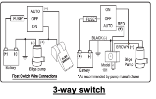
So, the “switch” which activates the pump is merely placed on the positive side of the circuit like this diagram, correct? Thus, it opens the circuit, or closes it, but only if the switch is in the automatic position?
The negative is direct to the equipment, and is never involved in any of the wiring other than that? Does this mean that only positive wires are involved in switches and fuses? (Forgive my electronic ignorance).
The negative is direct to the equipment, and is never involved in any of the wiring other than that? Does this mean that only positive wires are involved in switches and fuses? (Forgive my electronic ignorance).
Attachments
-
 Bilge_Wiring1-1959881456.gif3.4 KB · Views: 10
Last edited: