Different Approach
I have been pondering the question of what to do with my chainplates for many months now and I am slowly arriving at a solution. Instead of placing them externally, I am leaning towards replacing all six chainplates in the same deck location, but with a different configuration down below. This will preserve my pointing ability, which is highly desirable in a narrow waterway such as the Columbia River where the wind is often right on the nose.
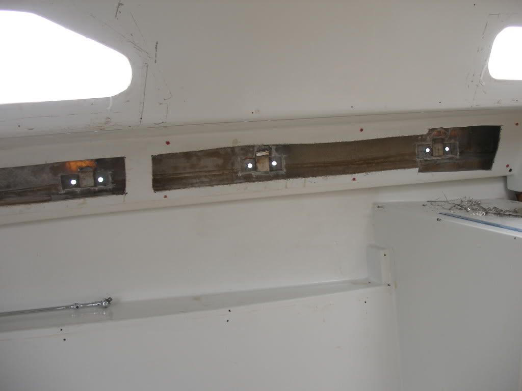
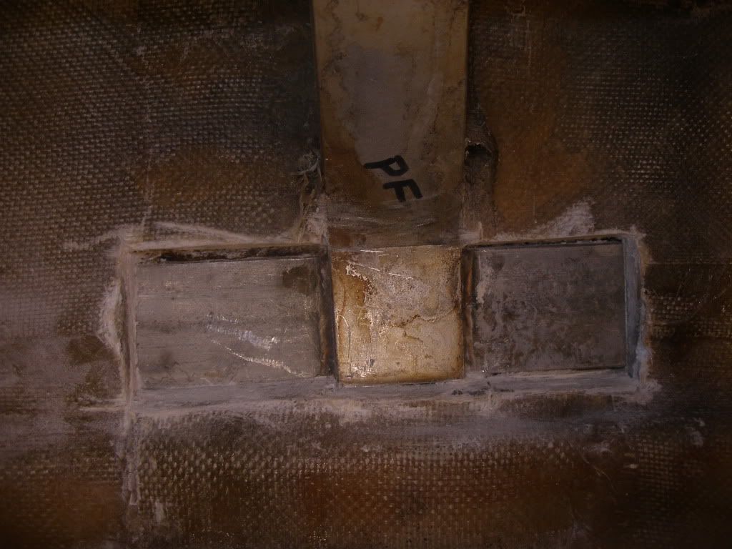
This photo shows the current situation below decks. I exposed the horizontal strap that connects the three chainplates. This is the port side forward chainplate, and the strap extends off to the left (aft). I did this to see what the condition of the welds were and also to make way for the next step. The welds look fine, but there is lots of rust coming down from the deck area, so I am suspicious of the chainplates up there. They had been sitting in wet core material for years.
So here is the plan:
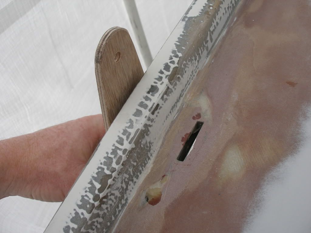
1. Cut off upright portion of chainplates at the crease shown in photos.
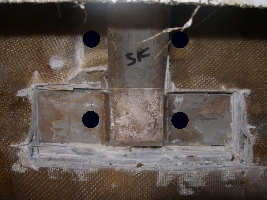
2. Drill 4 holes through hull at each chainplate. 2 of the holes will be through the existing metal strap (see diagram)
3. Build a pad at each chainplate area (or one big pad all the way across all 3) approximately 1 inch thick. Some combination of frp like G10 and biaxial cloth. Pad will extend up to the bottom of the deck and down as far as the bottom of the liner pan, and in towards the cabin far enough to allow the chainplate to mount flush against it and extend straight up through the existing deck exit slots.
4. Using holes already drilled on hull side, drill remainder of holes through pad.
5. Install SS backing plate on exterior of hull.
6. Install chainplate using 4 SS shoulder bolts.
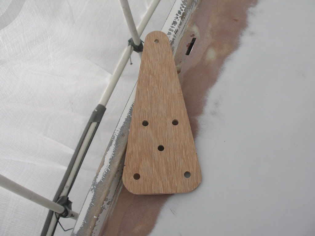
Here is a photo of the proposed hole locations
Of course this brings up a bunch of questions and issues I'll need to consider:
Hull backing plate- necessary or not, and if so, what kind and size of material? I don't think it would look very good, but if it's necessary, I'm more concerned about structural soundness than looks.
Pad build up. Should I add a layer of frp, or just use layer upon layer of biax?
Individual pads, or one large one the entire length of the strap? I also thought about glassing in a strip of frp above the strap for its entire length to add strength. The upper bolt holes would go through this strip.
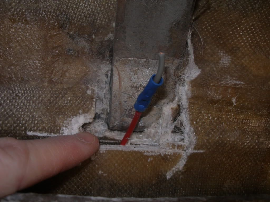
Liner issues. On the starboard side, the liner sits higher up than on the port. There is a void behind it which I will either have to fill with thickened epoxy somehow, or I will have to cut portions of it down. I don't want to leave a compressible space behind there. See photo below.
Sizing of through bolts and chainplates. I'll have to figure out existing rigging loads. The existing chainplate is 1/4 inch ss that is 1.5 inches wide. Right now I am thinking of upsizing everything a bit. 3/8 chainplates, 1/2" bolts perhaps. I like to overbuild stuff and I want the chainplates to be the strongest part of the rigging.
Here is a photo showing the liner issue. I could stuff the wire down between the hull and the inside liner that extends down to the starboard berth. Then there is the overhead liner glassed over this area. The liner is part of the structure of the boat so I don't want to try to take large sections of it out if possible. you can also see a void on each side of the chainplate area I cut out in the bolt hole photo above.
I see this being as strong or stronger than the original configuration, and will allow the chainplates to be removed and inspected periodically. The only weak spot I see would be the strap, which might still be subject to crevice corrosion if water were to get in. Of course I intend to properly seal all bolt holes and rebed them every so often to prevent this, so it shouldn't really be a problem for me.
Does this sound like a reasonable approach?
Thanks,
Doug
I have been pondering the question of what to do with my chainplates for many months now and I am slowly arriving at a solution. Instead of placing them externally, I am leaning towards replacing all six chainplates in the same deck location, but with a different configuration down below. This will preserve my pointing ability, which is highly desirable in a narrow waterway such as the Columbia River where the wind is often right on the nose.
This photo shows the current situation below decks. I exposed the horizontal strap that connects the three chainplates. This is the port side forward chainplate, and the strap extends off to the left (aft). I did this to see what the condition of the welds were and also to make way for the next step. The welds look fine, but there is lots of rust coming down from the deck area, so I am suspicious of the chainplates up there. They had been sitting in wet core material for years.
So here is the plan:
1. Cut off upright portion of chainplates at the crease shown in photos.
2. Drill 4 holes through hull at each chainplate. 2 of the holes will be through the existing metal strap (see diagram)
3. Build a pad at each chainplate area (or one big pad all the way across all 3) approximately 1 inch thick. Some combination of frp like G10 and biaxial cloth. Pad will extend up to the bottom of the deck and down as far as the bottom of the liner pan, and in towards the cabin far enough to allow the chainplate to mount flush against it and extend straight up through the existing deck exit slots.
4. Using holes already drilled on hull side, drill remainder of holes through pad.
5. Install SS backing plate on exterior of hull.
6. Install chainplate using 4 SS shoulder bolts.
Here is a photo of the proposed hole locations
Of course this brings up a bunch of questions and issues I'll need to consider:
Hull backing plate- necessary or not, and if so, what kind and size of material? I don't think it would look very good, but if it's necessary, I'm more concerned about structural soundness than looks.
Pad build up. Should I add a layer of frp, or just use layer upon layer of biax?
Individual pads, or one large one the entire length of the strap? I also thought about glassing in a strip of frp above the strap for its entire length to add strength. The upper bolt holes would go through this strip.
Liner issues. On the starboard side, the liner sits higher up than on the port. There is a void behind it which I will either have to fill with thickened epoxy somehow, or I will have to cut portions of it down. I don't want to leave a compressible space behind there. See photo below.
Sizing of through bolts and chainplates. I'll have to figure out existing rigging loads. The existing chainplate is 1/4 inch ss that is 1.5 inches wide. Right now I am thinking of upsizing everything a bit. 3/8 chainplates, 1/2" bolts perhaps. I like to overbuild stuff and I want the chainplates to be the strongest part of the rigging.
Here is a photo showing the liner issue. I could stuff the wire down between the hull and the inside liner that extends down to the starboard berth. Then there is the overhead liner glassed over this area. The liner is part of the structure of the boat so I don't want to try to take large sections of it out if possible. you can also see a void on each side of the chainplate area I cut out in the bolt hole photo above.
I see this being as strong or stronger than the original configuration, and will allow the chainplates to be removed and inspected periodically. The only weak spot I see would be the strap, which might still be subject to crevice corrosion if water were to get in. Of course I intend to properly seal all bolt holes and rebed them every so often to prevent this, so it shouldn't really be a problem for me.
Does this sound like a reasonable approach?
Thanks,
Doug