1. I don't think small wire and long charging routes would cause this problem because as the wire gets smaller and the route gets longer the effect of the engine on the battery goes away. It would become the same as the engine being off.
2. I should also add that this is an Ericson; wiring modifications come from this site, not Catalina site.

See:
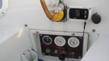
http://www.ericsonyachts.org/infoexchange/local_links.php?action=jump&catid=116&id=696 This was written for Universal Diesels, but would have the same effect on any engine with similar problems. Some people do not think the ammeter is useless on the diesel's instrument panel, I for one. I use it to monitor the engine loads, namely the glow plugs, solenoid, etc. YMMV.
Tom, I've read your contributions to this site and applaud you for them.
1. I think we need to differentiate between ammeters with internal shunts and external shunts in discussing appropriate use of ammeters in the cockpit. Most, if not all, production boats were built with ammeters with internal shunts, for reasons I mentioned earlier (cost), and the fact that they read 0-25A. For instance, the only Blue Seas ammeter with an internal shunt, model 8005, goes only to 25A, and is true for most ammeters, 'cuz for larger loads the shunts are too big to fit in the small ammeter housing. These are adequate for most on board uses, since while if you turned EVERYTHING electrical ON you'd most likely exceed that amperage, we rarely turn our fridge, running lights, ALL interior lights, steaming light, deck light, macerator and bilge pump, and whatever else we have, on at the same time. In the 13 years we've owned our current boat, the 0-25A internal shunt ammeter works just fine. This is NOT in the cockpit, but is down below, different from the factory installed cockpit ammeter.
Those are the types of ammeters most folks have in their cockpit panels, because that's what Universal provided with their cockpit panels, for our Catalinas and your Ericsons. They were also almost always provided with incredibly undersized small #10 wiring, a real voltage drop issue.
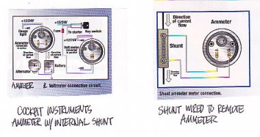
The photo on the LEFT below shows the internal shunt ammeter as installed. The downside of this is that ALL alternator output has to run all the way to the ammeter in the cockpit and then way back to the batteries to charge. That's why I made the point I did about the possibilities of electrical interference in the stereo installation.
However, there are, as you note, externally shunted ammeters, shown on the right. If the shunt is down below and the ONLY wires to the cockpit ammeter are the small wires from the shunt, then I agree it shouldn't be an issue, since they are only carrying a small amount of voltage with little current, only enough to move the meter. Thing is, these weren't the ones normally installed.
2. I agree, but we end up at the same conclusions, since Universal provided our engines and control panels. I did come across your referenced link in perusing this website and the earlier posts you've made, which have contributed greatly to the knowledgebase you have here. In fact, I came across just that link, but don't have the detailed historical perspective you have here to find and link it again. Point is, they both pretty much say the same thing. The Catalina one is from the "factory" and/or Universal, who would never admit to making a mistake, blaming the boat owners for putting too much electrical stuff on their boats where batteries would need a recharge! How dare those pesky boat owners!!! Oh well, at least we know about it.
I agree, an ammeter in the cockpit panel is truly helpful, but not if it is an internally shunted meter, because it messes up the charging system big time.
When discussing this many years ago, a friend suggested that the voltmeter can do the same thing: if the starter keeps working, or the glow plugs, the voltmeter will drop, providing the same functional indication that an ammeter would. I have found this to be true.