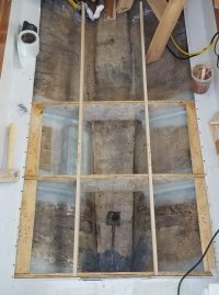
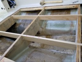
Floor frames were carefully measured and cut to float a cm off of the hull, glassed on both sides and epoxy sealed edges, then tabbed into place with 3 layers of 17 oz tabbing. A large 3/8" G-10 backing plate, big enough for the two cooling-water thruhulls & valves, was also glassed in at this time as the tabbing for the floors overlapped with it. This location will be under the galley extension/sink area, which should provide quick and easy access through a cabinet door. I never understood why many manufacturers hide the seacocks in near-impossible to reach areas -- all but guaranteeing the owner won't close them when they leave the boat..
The seawater strainers will also be located in this area, above and in line with the seacocks, arranged such that with the strainer removed a fiberglass rod can be snaked down from above to clear any obstructions in the thruhulls, should they become clogged.


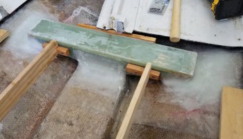
Now to the compression post step. I bought a big sheet of 1/2" G-10, cut out 8 laminations and a top plate with a diamond-abrasive wheel, epoxied them all together, and then tabbed the whole thing into the boat. It used the same 'gob-o-goo' mounting concept as the original step, though I used a mixture of cabosil, chop strand and 404 as filler, and tabbed everything in wet-on-wet on top of a large sheet of 17oz biax over the whole area as a tie-in. I used a lot of tabbing (5-7 layers, in different load directions) to try to spread load of the the rock solid G-10 out over a larger area, in an attempt to avoid hinging/point loading the hull. I spent a lot of time contemplating this repair, and while I know it's at least 10000% stronger than the original step, hinging/cracking of the hull scares the crap out of me. And this boat has been on a trailer for over 20 years -- the hull
is going to settle once it's back in the water. I can only hope that I spread the loads out far enough, and the substantial thickness of the hull in this location (somewhere between 1/2 and 3/4 of an inch) will be enough. Maybe I'm over-thinking and over-engineering, but better that than the alternative I suppose.


In the above photo I put the old rotten bottoms compression post back in while I took the main port-forward bulkhead out to use as a template to cut a new one out of 1/2" baltic birch. Baltic birch is a bit heavier than run of the mill fur/pine marine plywood, but it's the best quality wood I could find locally. (Since then, the local woodworker's source started carrying a couple thicknesses of marine ply but... I'll take the strength of the birch, thank you. Its a cruiser not a racer now lol) Fun fact, as a general rule, the 5x5 sheets of baltic birch usually use urea formaldehyde, and the the 8x4 and 10x5 panels use phenol-formaldehyde as used in exterior and marine ply. Check the color of the glue lines to be sure, the phenol ones are quite a bit darker.
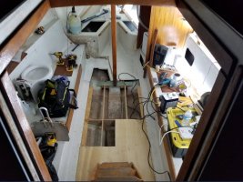
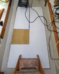
Below, you'll see the new cabin sole underlayment -- I glassed 1/2" baltic birch with 1708 on one side and 17 oz biax on the other, and painted the tops to keep the sun coming in the companionway from harming the epoxy. There are three pieces, the port-forward will support the water tank, there is a gap for the ply front of the new chaise lounge to structurally tie into the frames/step below. The wood-colored panel is a temporary cover for where the galley extension will be. The frames and floor stringers all had cleats/battens screwed to them to help spread the load out, and these panels will eventually be screwed to the cleats using probably machine screws and tee nuts -- I have a hunch the original sole-structure formed a triangle and contributes to the strengh of the hull, so I want it to be solidly fixed and able to carry shear loads, but also removable. An access panel will be cut in the aft-most panel, roughly where the original one was, to provide quick access to the sump.

With where the frames&cleats were tied into the existing fiberglass lip, and the thickness of the 1/2" + 1708 + 17 oz, the height of the panels is flush within a 16th of an inch with where the existing glass does its downturn to acomodate the old sole. This worked out exactly how I wanted it to, as the new sole will span that little depression (where you see the flathead screws tying it to the 3/4" ply runners above in the first pic) and run edge-to-edge with some sort of baseboard/trim. The original sole arrangement I felt made things feel smaller than it actually was. I love it when a plan comes together...
Oh, and it's SOO NICE to finally be able to walk around in there without twisting your damn ankles!!!


