• Untitled Document

    The 2024-2025 Fund Raising Season has Opened!

    EricsonYachts.org has opened the season for raising funds to support the expenses of the site. If you would like to participate, please see the link below for additional information.

    Thanks so much for your continued support of EricsonYachts.org!

    2024-2025 Fund Raising Info

Cabin Sole-how best to remove old sole [Master Thread]

nquigley

Sustaining Member
Yowzer! Super-nice work!

What thickness of marine ply did you use un the teak & holly layer, and what thickness of T&H did you order?
... assuming you're not laying the T&H directly on the TAFG.

Also - do you have a picture of the small forward-most bilge area? I think it has the forward-most keel bolt in it.
Are you going to make an inspection port for that bilge too?
 

Filkee

Sustaining Member
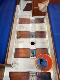
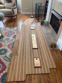
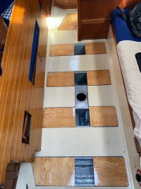
Yes, that was just the test fit. Still lots of detail work and a gazillion coats of varnish. The plywood is 1/4” and the bilge inserts are 1/2”. Christian has a posting earlier in this thread that shows how they come up together. 457F3C4B-B935-4831-B2DF-B83DC667F6B0.jpeg
I don’t think there are any bolts forward of the mast, but I’m still clearing debris. And yes, I’m going to cut access. Rethinking how many and where since the sole isn’t glued down anymore but I have pumps in two of the holes.
 

nquigley

Sustaining Member
Water definitely gets into that little forward bilge area - I've sucked it out many times with a hose poked through a hole that's just forward of the mast step, or through a small 'access' port in right wall of the storage area under the forward port-side settee.
I can't tell from your pic how water would get into it - can you tell?
Can you see a drain hole for it to empty into other bilge areas?
- given its inaccessibility, one might think it would drain to one of the aft bilges that's served by a pump.

Now I see the dimensions and shape of that bilge area - there wouldn't a keel bolt in there - it would be out-of-line with the others. Thanks!
 

Kenneth K

1985 32-3, Puget Sound
Blogs Author
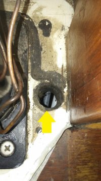
I was always told the forward 32-300 keel bolt is under the little hole in the sole just forward of the mast:

Keel bolt.jpg

I've never been able to see mine in there. Reportedly, the hole is barely big enough to get a socket into for the bolt. I wouldn't have any real issue with enlarging the hole if I thought I needed to.

The rest of the keel bolts are in the gelcoated, molded bilges. This one seems to just lie under the TAFG, which makes me wonder if it is sitting in water that I can't see most of the time. I keep my bilges dry, but it's harder to keep things dry under the TAFG, especially where you cant see.
 

nquigley

Sustaining Member
I was always told the forward 32-300 keel bolt is under the little hole in the sole just forward of the mast:

View attachment 36386

I've never been able to see mine in there. Reportedly, the hole is barely big enough to get a socket into for the bolt. I wouldn't have any real issue with enlarging the hole if I thought I needed to.

The rest of the keel bolts are in the gelcoated, molded bilges. This one seems to just lie under the TAFG, which makes me wonder if it is sitting in water that I can't see most of the time. I keep my bilges dry, but it's harder to keep things dry under the TAFG, especially where you cant see.
That's a great pic - I have a hole in the same place, but smaller diameter. I can usually suck some water out of that hole - which as you point out, must be under the TAGF pan, which I'd not thought of before. Thank you!
 

Christian Williams

E381 - Los Angeles
Senior Moderator
Blogs Author
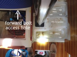
On my '85 32-3 there was an access port cut into the side of a locker for the forward keel bolt. Done with a jigsaw or handsaw, irregular shape, but big enough to get a long-handled ratchet wrench on. I also had the hole forward of the mast.

forward keel bolt access 32-3.JPG
 

nquigley

Sustaining Member
I thought I felt a bolt/nut when poking a hose through that access hole to get water out!
Do you think the little hole in front of the mast goes down to the same bilge area where that bolt is?
 

jrlago55

Junior Member
Yowzer! Super-nice work!

What thickness of marine ply did you use un the teak & holly layer, and what thickness of T&H did you order?
... assuming you're not laying the T&H directly on the TAFG.

Also - do you have a picture of the small forward-most bilge area? I think it has the forward-most keel bolt in it.
Are you going to make an inspection port for that bilge too?
I did the very same job on my E32-200. Looks like they use 3M 5200 silicon and as far as I can tell they did this to avoid the noise of the wood against the fiberglass. I use a spatula and some tugging but it was not a lot of effort to bring the sole out. I could not find a router bit to cut the curve edge around the sole do I built a template with the contour I also used a router bit to get me close to the contour the rest was sanded. But note that not all the edges have this contour.
Hope this helps.
 

jrlago55

Junior Member
I used 1” marine plywood with the teak and holly veneer. I did not replaced the most fire piece because it was the only salvageable piece. But I did unglue it. By the way I did not glue the sole back just because I rather have it removable. I’ll hunt for pics
 

jrlago55

Junior Member
I did the very same job on my E32-200. Looks like they use 3M 5200 silicon and as far as I can tell they did this to avoid the noise of the wood against the fiberglass. I use a spatula and some tugging but it was not a lot of effort to bring the sole out. I could not find a router bit to cut the curve edge around the sole do I built a template with the contour I also used a router bit to get me close to the contour the rest was sanded. But note that not all the edges have this contour.
Hope this helps.
By the way, I’m a rookie, It is Christian fault I got into sailing. Now I wonder why I did not got into it earlier in my life, simply put, I love it.
 

william.haas

1990 Ericson 28-2
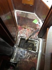
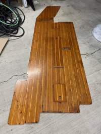
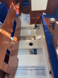
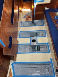
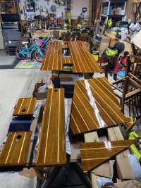
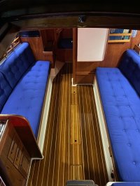
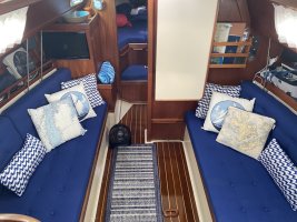
Hi all... I will eventually get around to a blog entry but for now a forum post. I completed the cabin sole on Danu and could not have done so without the help of many of you making posts, offering advice, and providing feedback. The old sole was tired, had some delamination from water damage, and it was time for an upgrade. I removed the old sole (thankfully it was not glued down), used the old as a template to make new pieces out of marine grade teak and holly plywood, epoxy sealed everything (all sides) with TotalBoat Clear Penetrating Epoxy Sealer, and then varnished with TotalBoat Gleam 2.0 Marine Spar Varnish (gloss). For the bilge boards, I actually routed out the old sole parts saving the frames and backings and epoxied in new, matching pieces of teak and holly plywood. While everything was out I cleaned, painted the bilge areas with TotalBoat TotalBilge Epoxy Sealer, and also traced and made new "subfloor" pieces out of marine grade plywood (also epoxy sealed). The fasteners were sourced from Fair Winds Fasteners and for the sole I went with silicon bronze flat heads with a square drive type. I used their "Screw Lube" product during the install and none broke on reassembly. Pictures throughout the process are added to the post.
 

Attachments

  • IMG_4081.jpg
    IMG_4081.jpg
    137.9 KB · Views: 39
  • IMG_4266.jpg
    IMG_4266.jpg
    208.9 KB · Views: 40
  • 66827643676__A1E79369-5E3E-482B-8CC6-7F7FCD57CF2F.jpg
    66827643676__A1E79369-5E3E-482B-8CC6-7F7FCD57CF2F.jpg
    181.5 KB · Views: 36
  • IMG_6146.jpg
    IMG_6146.jpg
    117.8 KB · Views: 33
  • IMG_6153.jpg
    IMG_6153.jpg
    153.2 KB · Views: 36
  • IMG_6237.jpg
    IMG_6237.jpg
    145.3 KB · Views: 32
  • IMG_6910.jpg
    IMG_6910.jpg
    229 KB · Views: 38
  • IMG_8011.jpg
    IMG_8011.jpg
    128 KB · Views: 40
  • IMG_8040.jpg
    IMG_8040.jpg
    277.7 KB · Views: 41

Bolo

Contributing Partner
Very nice and looks great. I replaced my T&H not too long ago on my E32-3 which when after I cut the pieces and laid them out in my garage took on a long “amoeba“ look with it’s cut outs and angles. Yours looks simpler in shape and it’s good you were able to salvage the old floor to use as a template. Two of my glued down old floor sections came up in toothpicks. Interesting how you have that one triangular shaped piece on the aft port side of the floor. Not that familiar with E28s. Why is isnt it part of the floor section it butts up against?
 

william.haas

1990 Ericson 28-2
Probably the curve from the hull shape.
Mark is correct… that little triangle is set at 30-ish degrees from horizontal (like a ramp). Also of note, some of edges of the sole pieces were 45s, some 30s, some 90s. Getting it all correct was quite the task and anyone taking on this task should note that when removing the old components (if possible).
 
Top