On our boat there were several places where the factory had zip-tied wiring bundles and some of the hose sections. It was challenging to work around those when time to run new hoses, etc. I did find that I could reach way under bunk tops with some side cutters and free the hoses, but it took time. Not fun.
You are using an out of date browser. It may not display this or other websites correctly.
You should upgrade or use an alternative browser.
You should upgrade or use an alternative browser.
Bilge Hose Replacement Battle
- Thread starter Nick J
- Start date
The short answer is no. The hoses were run in conduits through the TAFG, then secured to the plywood furniture. I'll try to pull up some pictures later when I have some more time.
The more I dig through my boat and look at pictures of the 32 and 38s the more I notice subtitle differences in the construction of each boat. Maybe Christian can add some insight here since he's owned a 32 and 38. In general it looks like the 32 is more modern with the TAFG incorporating more structure supporting the furniture and the 38 has the least amount of integration. The 35 seems to fit somewhere in between. A good example is the after section of the boats. When I look at Christian's videos and pictures of his stern the stringers look like they are glassed directly to the hull without any structure above. My 35 has stringers glassed in as well, but there's a separate piece of fiberglass on top of that. I didn't notice until I pulled the engine and cut the pan under the shaft log. This exposed the stringers and the connection between the hull and the extra piece of fiberglass. All three designs have their advantages and disadvantages. I envy the engine access on the 32 with the large removable panel and the 38 not having the extra piece of fiberglass for 40 years of dirt to get caught in. On the positive side, I don't have to deal with wires and hoses zip tied in inaccessible spots. Maybe this is just a sign of a company always trying to improve their design and manufacturing efficiency.
The more I dig through my boat and look at pictures of the 32 and 38s the more I notice subtitle differences in the construction of each boat. Maybe Christian can add some insight here since he's owned a 32 and 38. In general it looks like the 32 is more modern with the TAFG incorporating more structure supporting the furniture and the 38 has the least amount of integration. The 35 seems to fit somewhere in between. A good example is the after section of the boats. When I look at Christian's videos and pictures of his stern the stringers look like they are glassed directly to the hull without any structure above. My 35 has stringers glassed in as well, but there's a separate piece of fiberglass on top of that. I didn't notice until I pulled the engine and cut the pan under the shaft log. This exposed the stringers and the connection between the hull and the extra piece of fiberglass. All three designs have their advantages and disadvantages. I envy the engine access on the 32 with the large removable panel and the 38 not having the extra piece of fiberglass for 40 years of dirt to get caught in. On the positive side, I don't have to deal with wires and hoses zip tied in inaccessible spots. Maybe this is just a sign of a company always trying to improve their design and manufacturing efficiency.
Here's some pictures of my 35-3
Cut-out of stern pan where thru hulls exit:

in comparison, see Christians 38 in his Wind Vane Blog:
 ericsonyachts.org
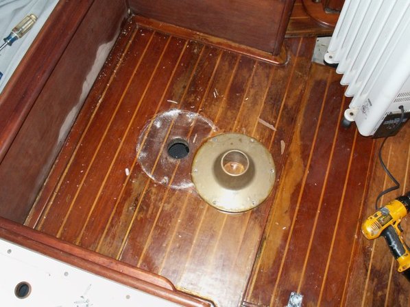
Here's the same pan under the shaft log before I cut it out:

It shows how the stern pan overlaps the TAFG which contains the engine bed
Here's a pic of it cut out:

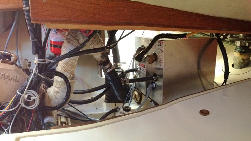
You can see how the TAFTG is glassed to the hull and the stern pan is placed over the assembly (water lift muffler and water heater removed for the strut work). Compare this to the 32 in Christian's water heater replacement blog:
 ericsonyachts.org
For the actual plumbing routing, treilley has some great pics on his project page at:
 tkronaboat.com
Here's some pics of the plumbing once it rises above the TAFG and attaches to the furniture:
Cut-out of stern pan where thru hulls exit:
in comparison, see Christians 38 in his Wind Vane Blog:
E381 - Cape Horn Wind Vane Installation 2021
Links to videos at the end of the post. The "integral" Cape Horn vane connects the servo-pendulum gear by lines to the ship's quadrant by means of its own quadrant installed on the interior transom. Unlike other servo-pendulum systems, all the...
Here's the same pan under the shaft log before I cut it out:
It shows how the stern pan overlaps the TAFG which contains the engine bed
Here's a pic of it cut out:
You can see how the TAFTG is glassed to the hull and the stern pan is placed over the assembly (water lift muffler and water heater removed for the strut work). Compare this to the 32 in Christian's water heater replacement blog:
E32-3 - Water Heater Replacement, Raritan to WM/Kuuma
The 1985 Raritan 6-gallon water heater still worked without complaint, heating fine while under power and keeping the water warm until breakfast the next morning. The electrical heater no longer functioned, but then I never had cause for hot...
For the actual plumbing routing, treilley has some great pics on his project page at:
Cabin Sole Replacement
When we bought the boat it had a distinct diesel smell from a fuel tank leak. The diesel fuel had soaked into the cabin sole and ruined it. We decided the only way to resolve this was to replace the...
tkronaboat.com
Here's some pics of the plumbing once it rises above the TAFG and attaches to the furniture:


Yeah, that pan below the shaft coupling is a bit of a curiosity (the 32-3 has the same). The pan traps water and, thus, requires the PVC drain tube that runs through the engine bed.
Without the pan, water would simply run below the TAFG and find its way into the bilges. Seems like both the pan and the drain tube are better eliminated. But then the drain tube holes in the engine bed would need to be sealed back up.

Without the pan, water would simply run below the TAFG and find its way into the bilges. Seems like both the pan and the drain tube are better eliminated. But then the drain tube holes in the engine bed would need to be sealed back up.
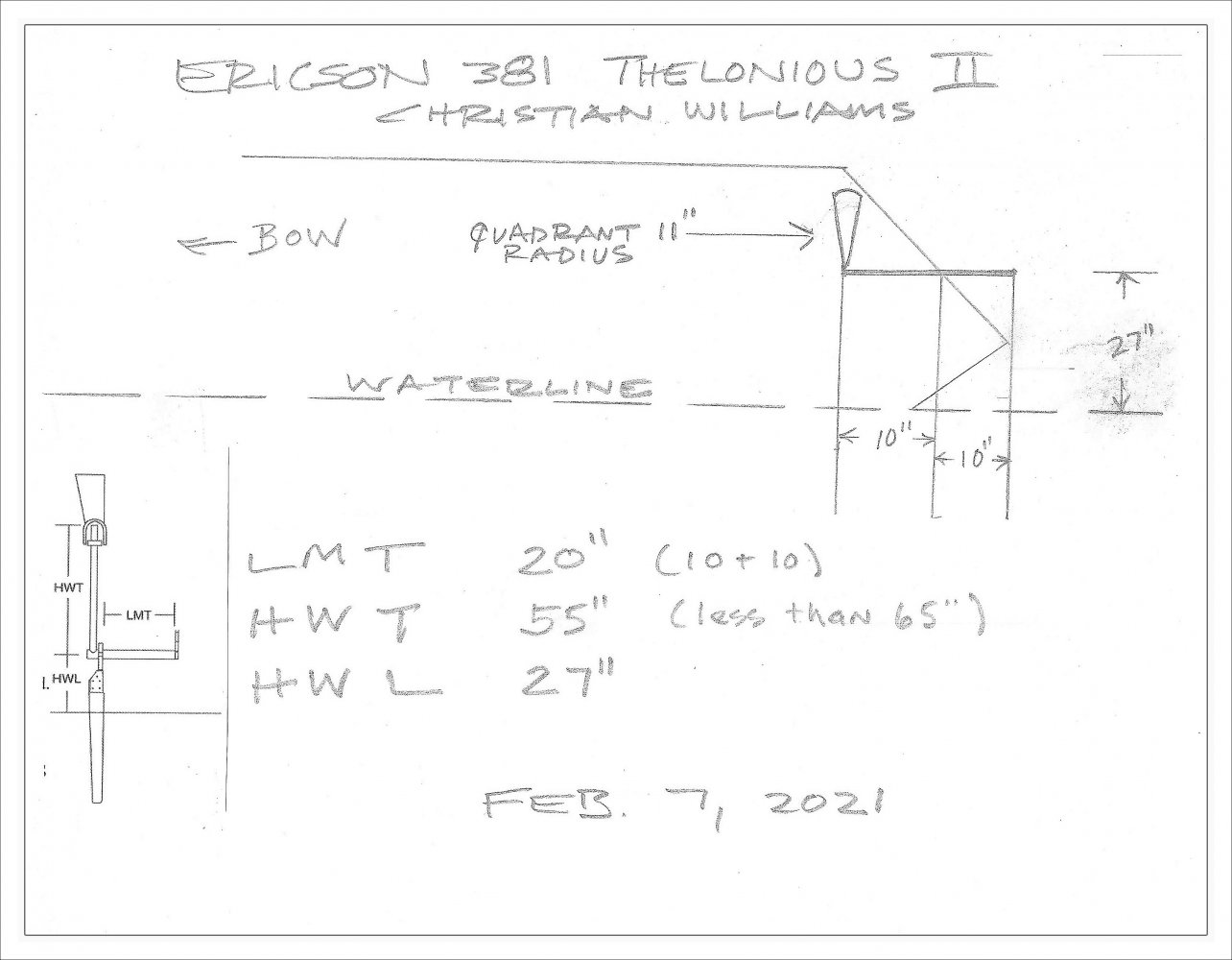
The entrance to the tube is between the hull and the pan. Kind of hard to explain, but here's a crude sketch:

I think Ericson tried to limit the water ingress into the TAFG, but didn't end up executing the plan very well. Water that enters the boat through the stuffing box will make its way to the bilge through the drain tube. It's sealed off from the TAFG by the tabbing and the drain tube while bypassing the engine pan. Good idea, but I don't think all the tabbing 100% seals the TAFG cavities and the limber holes in the bilge are all just cut out instead of drain tubes like above. The area between the stern pan and the TAFG on my boat was completely filled with oil soaked mud and gunk which blocked the drain tube.

I think removing the stern pan section to access the drain tube is the best fix here. It's also a good idea to cut an access hatch at the other end of the tube so you can reach both ends.
I think Ericson tried to limit the water ingress into the TAFG, but didn't end up executing the plan very well. Water that enters the boat through the stuffing box will make its way to the bilge through the drain tube. It's sealed off from the TAFG by the tabbing and the drain tube while bypassing the engine pan. Good idea, but I don't think all the tabbing 100% seals the TAFG cavities and the limber holes in the bilge are all just cut out instead of drain tubes like above. The area between the stern pan and the TAFG on my boat was completely filled with oil soaked mud and gunk which blocked the drain tube.
I think removing the stern pan section to access the drain tube is the best fix here. It's also a good idea to cut an access hatch at the other end of the tube so you can reach both ends.
The entrance to the tube is between the hull and the pan. Kind of hard to explain, but here's a crude sketch...
Ok, then that's different from the 32-3. Mine has the aft end of the drain tube above the pan. Water from the prop shaft log (I had a PSS failure in 2020) can drain under the "stern pan" without entering the drain tube. If the engine pan is tabbed to the hull (makes sense it would be) perhaps there is drainage space outwards (to port/starbd) of the tabbing.
I'd hazard a guess that the same would be true on the larger boats too, since a gravity-fed 3/4 to 1" PVC tube would likely be insufficient to dewater the aft third of a boat in many situations.
I ordered PEX 1/2 to PEX 3/8 reducer and Pex 3/8 to PB 3/8 converter. both use the same clamps I've been using for the rest of the system. The converters haven't arrived yet and when I was mention the problem to one of part guys at Harbor Marine, he showed me these:
 www.acehardware.com
Picture reused from the https://ericsonyachts.org/ie/threads/plumbing-access.20433/#post-162183 thread showing the install:

I figured they are easily removable and have 2 fewer connections than the clamp based solution, so I'm going to give them a try. I should be able to test the system next weekend. If it doesn't work, I'll go back to the clamp solution above.
Flair-It 1/2 in. PEX X 3/8 in. D PEX PVC Reducing Coupling Mfr# 16853 - Ace Hardware
Flair-It fittings are constructed of durable Polyoxymethylene (POM) and are compatible with PEX and PB. The patented design consists of a nut and flared insert and requires no tools. The fittings push against the ID and OD of the pipe, creating a strong long-term seal. Flair-It fittings are...
Picture reused from the https://ericsonyachts.org/ie/threads/plumbing-access.20433/#post-162183 thread showing the install:
I figured they are easily removable and have 2 fewer connections than the clamp based solution, so I'm going to give them a try. I should be able to test the system next weekend. If it doesn't work, I'll go back to the clamp solution above.
Ref: Our discussion in posts 24-26 about the "stern pan." Here are photos of how my '85 32-3 is laid out:


Water can drain below the pan (along the hull) or above the pan (through the PVC tube). I used to tuck my water-lift muffler drain (the red tube) an inch or two under the pan. The muffler would drain into the bilge, leaving black soot in the bilges. Now I run the red tubing through the PVC tube and all the way to the bilge, so I can collect the sooty muffler water in a cup.
Water can drain below the pan (along the hull) or above the pan (through the PVC tube). I used to tuck my water-lift muffler drain (the red tube) an inch or two under the pan. The muffler would drain into the bilge, leaving black soot in the bilges. Now I run the red tubing through the PVC tube and all the way to the bilge, so I can collect the sooty muffler water in a cup.
Last edited:
Wow, great pics Ken! So interesting how the subtle difference make a big difference. The 32-3 looks like the stern pan is actually part of the TAFG. Much easier to clean without a gap between the TAFG and stern pan. If the passage between the TAFG and Hull gets blocked, the water will only build up to the drain tube then drain to the bilge.
I like your idea with the muffler drain. I just have a hose barb sticking out of a petcock. When I need to drain it, I just put a cup under and open the valve. It takes me quite a few cups until the muffler is empty. Your solution is much better.
I also can't get over how much better the engine access is on the 32-3. Being able to remove the whole port forward corner and the panel by the quarter birth is awesome.
It is! But laying on one side with a headlamp on while holding tools out in front of you will give you a sore neck for days.Being able to remove the whole port forward corner and the panel by the quarter birth is awesome.
Here's the final bilge hose configuration as it exist the conduits passing under the engine stringers. The hoses had to be configured exactly that way to make them fit in the conduit. It made it a little messy as it exited, but I think it's a huge improvement over the original configuration.

Here's what the compartment just forward of the engine looks like:

Here's what the compartment just forward of the engine looks like:
some more pics of the overall run from the aft locker to under the aft section of the port settee.
aft locker thru hull:

passing under the Starboard seciont of the "T" cockpit:

continuing forward along the edge of the cockpit sole:

diving down the starboard side of the engine compartment:

Another pic of it entering the conduit below the engine stringer:

(see previous post for it exiting the stringer conduit and passing from starboard to port)
End of the run in the aft section of the port side settee where I will install the two bilge pumps (there's also the pickup to the main bilge compartment installed):

aft locker thru hull:
passing under the Starboard seciont of the "T" cockpit:
continuing forward along the edge of the cockpit sole:
diving down the starboard side of the engine compartment:
Another pic of it entering the conduit below the engine stringer:
(see previous post for it exiting the stringer conduit and passing from starboard to port)
End of the run in the aft section of the port side settee where I will install the two bilge pumps (there's also the pickup to the main bilge compartment installed):
peaman
Sustaining Member
Yeah, no kidding. I wonder how thick is the glass in the stringers? Every new hole in my boat makes me nervous, and lately, I've put in a few.but I'd be pretty nervous drilling that first hole.


One thing about a hole saw is that it delivers intact the disk of glass it cuts out. I've always felt I could always undo the hole by epoxying the desk back in. Takes some of the terror out of big holes--such as the 3 1/2" one the Cape Horn install required in my transom.
Alan Gomes
Sustaining Partner
Those are from my boat. Bear in mind that I have an E26-2, in case that should make any difference as far as the thicknesses are concerned.I think it's been done. As in these photos from a post about fixing loose engine mount lag bolts:
View attachment 45925 View attachment 45926
I think I'd have to start with a smaller hole, then an inspection camera before cutting a hole this big.
I'm not even slightly worried about the strength of those stringers, by the way. They are substantial. Additionally, my 1GM weighs around 130 lbs. all in, give or take.
We slid a threaded metal plate into that hole and slid it forward to meet up with a regular threaded bolt. This required some tilting of the plate to line up the threads, hence the size of the hole. For some odd reason I failed to take a photo with the plate finally installed, but in the final installation the plate protrudes slightly aft of the stringer, making it possible to hold it and adjust its position for assembly/disassembly.
Here is a picture of the plate itself.

Last edited:
Thanks Alan. I kept those photos in case I someday need to address my engine mounts too.Those are from my boat. Bear in mind that I have an E26-2, in case that should make any difference as far as the thicknesses are concerned.
I wouldn't be either.I'm not even slightly worried about the strength of those stringers, by the way.
Last edited:
I really like this approach. If I ever have to do this particular job again I will use this method (instead of hanger bolts). Nice work.We slid a threaded metal plate into that hole and slid it forward to meet up with a regular threaded bolt.
I'm getting closer to wrapping up the bilge pump project. We installed the two vane pumps yesterday. They work much better than the centrifugal pump if your comparison is based on amount of water removed. one down side is the noise. The pumps are isolated from the mount with rubber feet which keep the actual pump quite, but the noise of the vane spinning is quite loud and come primarily from the end of the hose in the bilge. Having a noisy bilge pump may not be a bad idea though, now I don't have to install a high water alarm.
The pumps are located in the aft compartment of the port settee on the panel near the center of the boat. Everything fit neatly under the lip of the hatch opening, so it doesn't get in the way too much. I used a relay to control the shower pump due to the long run between the battery, head mounted switch, water witch switch in the bilge, and pump location. I left the shower water witch switch at home so I wasn't able to test yesterday. I'll reserve final judgement until we get some time with the new configuration, bus so far so good!

The pumps are located in the aft compartment of the port settee on the panel near the center of the boat. Everything fit neatly under the lip of the hatch opening, so it doesn't get in the way too much. I used a relay to control the shower pump due to the long run between the battery, head mounted switch, water witch switch in the bilge, and pump location. I left the shower water witch switch at home so I wasn't able to test yesterday. I'll reserve final judgement until we get some time with the new configuration, bus so far so good!