• Untitled Document

    Join us on April 26th, 7pm EST

    for the CBEC Virtual Meeting

    All EYO members and followers are welcome to join the fun and get to know the guest speaker!

    See the link below for login credentials and join us!

    April Meeting Info

    (dismiss this notice by hitting 'X', upper right)

E35-3 Aft-led lines and Traveler Setup

MarineCityBrian

Apprentice Tinkerer
I had cam cleats like Cory's and replaced them with Spinlock PXR cleats because they are MUCH easier to release under load. My crew, and her leader, is getting a little long of tooth. :rolleyes:

Tom - if you don't mind my asking which version of the Spinlock PXR cam cleat did you purchase? I know which version in terms of line size capability, but I'm between the direct mount and the swivel mount version; the latter to "aim" the cleat more toward the raised fixed block on the tower to reduce friction as much as possible (though I worry the swivel is not necessarily in a fixed positron once secured to the deck).
Come spring I'll have many more updates as I install things and test functionality for both the at led line setup and the traveller setup.
I much appreciate the help I've received! Thank you all so much!
 

MarineCityBrian

Apprentice Tinkerer
In the following pictures on the starboard side (left to right) is 75 reef, main sheet, and main halyard. On the port side (left to right)is the jib halyard, 50 reef, and toping lift for wisker pole. As far as I am aware all these lines were led aft from the factory according to the paper work I have from the factory. Except for the topping lift which appears to have originally been a cunningham control line location. The out haul and cunningham are located on the boom and mast respectively. If I am single handing these are two control lines i don't want or need in the cockpit so I am good with this set up. As far as the traveler set up i am fine with it. It works well and except for the cleats.... but this will soon be fixed.

Darrel,
Thanks SO MUCH for the lovely photographs! These are exactly what I needed to go forward with my proposals. Still trying to think through racing maneuvers (as well as convenience for daysailing) to optimize the line layout, but both the forum and photos are of great assistance.

Thanks again, and happy sailing!
 

Loren Beach

O34 - Portland, OR
Senior Moderator
Blogs Author
Clutch technology and location

In the following pictures on the starboard side (left to right) is 75 reef, main sheet, and main halyard. On the port side (left to right)is the jib halyard, 50 reef, and toping lift for wisker pole. As far as I am aware all these lines were led aft from the factory according to the paper work I have from the factory. Except for the topping lift which appears to have originally been a cunningham control line location. The out haul and cunningham are located on the boom and mast respectively. If I am single handing these are two control lines i don't want or need in the cockpit so I am good with this set up. As far as the traveler set up i am fine with it. It works well and except for the cleats.... but this will soon be fixed.

The pix show (nowadays maligned, and deservedly so) "old fashioned" line jammers. Those things will eat the cover on your spendy halyard tails. Stubborn-difficult to release under load.

Several clutch designs have evolved since those were installed, and any of 'em would be better. I prefer the "falling rings" design of the Lewmar's, and YMMV.

Also there is the location of the stopper grouping. I see that like our boat yours are forward a ways on the housetop on either side of the hatch opening.
This was to make the boat a bit more efficient for buoy racing involving a lot of mark rounding and attendant changing back n forth between spinnaker and jibs and also inhaling/exhaling line tensions for changing the shape of the main. This allowed for a crew person to be stationed in the companionway to work all those lines, stoppers(clutches) and winches, and is often referred to as the "pit" position. This usually keeps this person out of the sheet-handling tacking-melee in the cockpit.

When/If we install a "cruising dodger" we will move the clutch banks and winches closer to the rear of the housetop. This will make reaching all this stuff a lot easier and much reduce conflicts with the inside of said dodger.

Loren
 

MarineCityBrian

Apprentice Tinkerer
Brian - I went with the fixed mount. I like simple (& cheap). I also think being shorter causes less interference with other lines on the cabin top.

Tom - Thanks for the feedback. I agree that's the best. In looking at the swivel, while the base looked spherical, it's just a side-to-side swivel action, not any other direction, and I believe it will always swivel (not fixed in one position). So, I think the standard base is ideal, and if not "aimed" correctly at the fixed traveler block on the tower (such that it feels as though it's imparting too much friction), I'll merely put a small teak riser 'wedge' beneath it to get the proper angle.

Thanks again!
 

Darrel

Member I
The pix show (nowadays maligned, and deservedly so) "old fashioned" line jammers. Those things will eat the cover on your spendy halyard tails. Stubborn-difficult to release under load.

Several clutch designs have evolved since those were installed, and any of 'em would be better. I prefer the "falling rings" design of the Lewmar's, and YMMV.

Also there is the location of the stopper grouping. I see that like our boat yours are forward a ways on the housetop on either side of the hatch opening.
This was to make the boat a bit more efficient for buoy racing involving a lot of mark rounding and attendant changing back n forth between spinnaker and jibs and also inhaling/exhaling line tensions for changing the shape of the main. This allowed for a crew person to be stationed in the companionway to work all those lines, stoppers(clutches) and winches, and is often referred to as the "pit" position. This usually keeps this person out of the sheet-handling tacking-melee in the cockpit.

When/If we install a "cruising dodger" we will move the clutch banks and winches closer to the rear of the housetop. This will make reaching all this stuff a lot easier and much reduce conflicts with the inside of said dodger.

Loren

Loren,
Thanks for the input. Yes i intend on replacing the jammers before the summer season. I usually bungee the main sheet jammer open so the line can run free when i need it to and use the self tailoring wench to hold the sheet which works as it is a dedicated winch and the main halyard uses a standard cleat it it had a jammer that would have been the first to go. I believe in being able to quickly douse the main if i need to. I personally like simplicity in my hardware...... less to break.:) So still debating on a clutch or cleats.

My boat has all the cabin top mounting for a dodger and was wondering if anyone on here knows the or where to get the original dodger. That is the next "big" project my boss has informed me she wants done. I have though about reorganizing the layout due to personal preferences and future dodger but haven't thought that far ahead.

My project list is long but not as long as it was when i purchased the boat six months ago. currently it is going through and rebuilding/replacing non-working items from the boat being unused the past 4 years. But she sails like a dream and always turns heads on the water.

Darrel
E 35-3 #154
s/v "Sunflower"
 

Darrel

Member I
Darrel,
Thanks SO MUCH for the lovely photographs! These are exactly what I needed to go forward with my proposals. Still trying to think through racing maneuvers (as well as convenience for daysailing) to optimize the line layout, but both the forum and photos are of great assistance.

Thanks again, and happy sailing!

Brian,
NOT A PROBLEM at all !! One thought I have been having is using a continuous Jib/Gen sheet. This, from what I have read, is a preferable set up for single handing and keeps the large pile of sheet down to a minimum in the cockpit. And if I don't like it, well its nothing a knife and whipping twine won't fix. But I may give it a try for grins and giggles. :)

I have thought about reorganizing the line lay out but not quite sure how or when Ill get to it. As it works fine now and I am getting use to the lay out so it will probably be moved down the list as it is not a priority. But when the dodger is built and installed I know it will require some attention at that point.

Darrel

E35-3 #154
s/v "Sunflower"
 

MarineCityBrian

Apprentice Tinkerer
Ronstan fixed block and cam cleat fix

In my progress with this project I've discovered at least 2 of the reasons why the outer fixed blocks are so difficult to cleat and let slack on. For cleating, I believe the issue to be from the poor design of each cam's jaws. They are not a smooth progressive taper, but rather a blunt chamfer that prevents line from readily separating the jaws:
2017-01-31 11.32.53.jpg

To solve that issue I did the following:
1. Removed each jaw from the assembly (just requires a slotted screwdriver).
2. Filed down the tooth of each cam to achieve the progressive taper I desired.
2017-01-31 11.34.08.jpg
3. Once I achieved the taper I liked, I next worked to bring the remainder of the tooth to this new profile, effectively "re-sharpening" each tooth. I achieved this with a combination flat / round file (one side is flat, the other has a large radius curve and the edge is somewhat sharp).
2017-01-31 11.35.00.jpg
First tooth complete (above)
2017-01-31 11.35.51.jpg
All teeth complete (above)
4. Once I re-sharpened all of the teeth I cleaned up and smoothed out my work on a wire wheel:
2017-01-31 11.36.52.jpg
I can say based on a back-to-back comparison the smooth taper cleat operates MUCH more easily than the previous cleat with the abrupt chamfer. Almost effortless. And it really only took simple hand tools (with the exception of the wire wheel which I have on my bench grinder). I'd also like to take my Dremel polishing wheel to them for additional smoothness and use a polish such as Flitz which would also offer corrosion protection.

Now, all of that said I have thinned-out the section and wall thickness of each cam, so technically I've weakened it. So, before anyone goes trying this just be cognizant of that risk. The cams appear to be made from brass as you can see from the picture, so I don't forsee any issues but wanted to give fair warning. I did not break through the wall anywhere I filed, and the cam tooth portion had the thickest wall on the part, but again, consider yourself warned.
 
Last edited:

supersailor

Contributing Partner
Great post! I always thought about doing this but never did. After everything else gets done, I will do the three I have on board.
 

MarineCityBrian

Apprentice Tinkerer
Ronstan fixed block and cam cleat fix

The 2nd issue with these blocks is their propensity to bind on easing. I've found this to largely be the fault of Ericson specifying 3/8" line for the traveler as well as (and perhaps more significantly) the use of a flat block plate above the bottom sheave, where the traveler line exits to the cam cleat. On the top sheave, Ronstan originally riveted a formed plate:
2016-12-29 12.36.53.jpg
My thought is that this was for stiffness, since this is the furthest plate from the fixing point, and hence would endure the largest bending force. Since this forming does not extend past the outboard rivet, it doesn't really prevent the block from bending (as you can clearly see above). So, my suggestion is to swap where the flat and formed plates go, and place this formed plate above the bottom sheave such that it provides a guide for the traveler line. In the below instance, I've also added a sheave (I was fortunate enough to receive the boat with a spare broken block, which I was able to scavenge parts from) since I'm going to try going 5:1 rather than the stock 3:1, and use smaller line with a similar strength to the original 3/8" (though factored less for the reduction in load due to additional purchase). You can see how stacking the formed plate on top of the bottom sheave makes for a nice line guide and doesn't interfere with the sheave above either:
2017-01-31 12.33.29.jpg

Obviously once complete I will trim the bolts to the proper length and use Nylock nuts, but this is the general theory. If your system worked fine in terms of slacking then this may not be for you (since it would require drilling out your rivets), but in my case all the outboard blocks I had were bent and in major need of repair. I also plan on replacing these sheaves with ball bearing versions from Garhauer (they will sell you #25 Self-Contained Ball-Bearing sheaves individually). An alternative would be the Harken ball bearing sheave available from Amazon, but this is 1.5" (smaller than original) and would require you to make your own spacers on the opposite side.
 
Last edited:

Christian Williams

E381 - Los Angeles
Senior Moderator
Blogs Author
Great to see original equipment brought back to life.

To conclude my saga: I found the original becket blocks and converted the traveler system back to what appeared to be the original 3:1. With the becket blocks on the car, when the traveler went two-block it made a mess. The becket jammed in the knots and the collision of fittings had a 4" gap. Huh.

Mind you, this experiment was on the theory that the original setup was 3:1, based on gear left on board.

My PO had (also) drilled out the pins in the Ronstan blocks and replaced them with bolts so he could add a stainless loop on top as a becket. That gave 4:1.

I went back to his system, but since his invented becket looked odd (see pic in Post #29), I moved it to the other pin, where the pull is more true.

This modification--the history of which is guesswork--now works rather well and even looks pretty good.

Who needs ball bearings?

1-Ronstan revised.JPG1-traveler revised.JPG
 
Last edited:

MarineCityBrian

Apprentice Tinkerer
I do, between all 3 fixed blocks, still have 4 decent sheaves, so I could easily go back to that (or keep it) if necessary (this winter's projects are becoming pretty spendy pretty quick, so...). It would still require a double block in the movable car either way. One question: do you knew where to procure those stainless loops? I couldn't readily find any on a couple sites I checked.
Regarding the way the 3:1 system binds when coming together, I've experienced the same thing. Another reason why I'd like to change....

On ball bearing blocks, wasn't it Irwin Fletcher who said, "It's all ball bearings these days!" :)
My thought was merely for long lasting reduced friction, and since the Garhauer blocks are reasonably priced (similar to a replacement Delrin sheave) I figured I couldn't go wrong. Additionally the increased bearing area of each ball bearing sheave would make each block much stronger and resist it from going "parallelogram" as mine did.

I'm also envious of your ball bearing Garhauer fiddle block for your main sheet. ;)

Lastly, have you ever had trouble slacking your traveler, and considered positioning your formed plate in the position I mention above? Just curious if you think that would help.
 
Last edited:

Christian Williams

E381 - Los Angeles
Senior Moderator
Blogs Author
I recalled your idea when I had the blocks apart, and you;re probably right. Or maybe that block set had another optional setup, in which the the relieved top had a purpose.

In any case, my traveler goes down easily. Yeah, the lines bunch up on the downhill side, but that's life with this rig.

I don't know the oirgin of that strap. Might simply be a re-purposed eye strap, although they aren;t usualyl flat like that nowadays.

Anybody recognize this stainless "loop"?

Ronstan revised - Copy.jpg
 

MarineCityBrian

Apprentice Tinkerer
Traveler set-up complete...

To further this thread, I've finally rebuilt the traveler outer blocks (fixed blocks) with the Garhauer ball bearing sheaves (I couldn't resist, and they really operate much more smoothly) and the Ronstan Beckets. The Ronstan Becket has a more abrupt transition to the loop than the ones from Christian's set-up, but work fine. To counter this I threaded the nut on a piece of cut-off bolt, chucked it in my cordless drill and with the drill slowly rotating held it against my bench grinder to make a bit of a chamfer/cove at the bottom of the nut so it would rest squarely on the flat of the Becket. In doing more research, I believe Christian's Becket to be this Schaefer product:

http://www.defender.com/product.jsp?path=-1|118|2358559|2358566&id=117000

I like the more rounded/formed loop of the Ronstan, but the greater flat area on the Schaefer. Now you can make your own choice. I decided to go with a continuous loop for the traveler line (but with enough such that if I find it cumbersome it can be cut into two separate lines), and went with NE Ropes "BUZZ line". Soft on the hands and plenty strong, and pretty cheap too. Only drawback is it is not readily splicable, so stopper knots do the trick at each Becket. I went with some Ronstan Orbit double blocks that exceed the load capacity of the original Schaefer blocks. Here are photos of the set-up:
 

Attachments

  • 2017-04-30 13.58.37.jpg
    2017-04-30 13.58.37.jpg
    86.4 KB · Views: 50
  • 2017-04-30 13.59.17.jpg
    2017-04-30 13.59.17.jpg
    79.3 KB · Views: 46
  • 2017-04-30 13.59.57.jpg
    2017-04-30 13.59.57.jpg
    79.1 KB · Views: 45
  • 2017-04-30 14.00.24.jpg
    2017-04-30 14.00.24.jpg
    77.1 KB · Views: 48
Last edited:

MarineCityBrian

Apprentice Tinkerer
Traveler set-up complete...one thing to note with Garhauer Sheaves

One thing to note with the Garhauer sheaves: they are slightly larger in diameter than the original sheaves, so when placing the formed plate between the sheaves (as works best to guide the line out of the jaws of the cam cleat), you must un-bend this forming slightly. I achieved this with a pair of vice grips, and the result is quite nice:
2017-04-30 15.25.16.jpg

Next, it's important to remember when ordering the sheaves from Garhauer to also order the same thickness bushings (they are slightly different in thickness from the Ronstan sheave bushings). They apparently didn't have any 1/4" ID bushings in stock so they sent 5/16" - no big deal and they work fine:
2017-04-30 15.26.19.jpg
Again - the items to order are "#25 Self-Contained Ball Bearing Sheaves." Price each at the time I ordered: $16/ sheave, $4/bushing (the bushings have no part number, you just have to request them).

Next few photos detail the assembly process and the order in which the plates should be stacked:
2017-04-30 15.26.53.jpg
You can see in this picture the "un-bending" I did to the formed plate (which, in my opinion should go in the middle in order to better guide the line from the cam cleat):
2017-04-30 15.27.27.jpg

Apply the 2nd sheave and bushing:
2017-04-30 15.28.41.jpg

Finally install the top plate, Becket (If you're converting from 3:1 to 4:1 like I did) and nuts.

Final product can be seen in the pics from the previous post. Note that the bolts will need to be trimmed to size.
 
Last edited:

Christian Williams

E381 - Los Angeles
Senior Moderator
Blogs Author
Very useful stuff. Let us know how the single-piece line works. I have my doubts, since I find a straight pull, braced in the cockpit, easiest in popping out and setting in the line.
 

MarineCityBrian

Apprentice Tinkerer
Very useful stuff. Let us know how the single-piece line works. I have my doubts, since I find a straight pull, braced in the cockpit, easiest in popping out and setting in the line.

I will. I've got enough line there to cut it and do as you suggest (which is the plan should it fail) but with the zero-cost opportunity to run the experiment as to whether it will or won't work I jumped at the chance. The photo is deceptive because I have the remainder coiled up beyond the starboard fixed block for neatness in the photo. It actually hangs down around the cabin entry with slack.
 

MarineCityBrian

Apprentice Tinkerer
Aft Led Lines Follow-Up (Progress - Part 1 of 4)

I've added some of the aft-led lines and deck hardware earlier in the season, but am just now getting around to posting about it.

Some brief highlights of the things I did:

1. CAREFULLY removed the headliner (though I did make 1 cut that I'll replace with a zipper to get around the mast, but I don't see this as such a bad thing for future access)
2. Over-drilled each thru-deck hole from the bottom side with a 1-1/8" hole-saw (after drilling a pilot hole from the topside, after marking the hardware location), checked the deck plywood laminate for moisture (yes, there were a few moist areas...:esad:, but I'll address that later), and filled with West Systems 406 filler thickened epoxy (for what it's worth I used fast-cure hardener). I then re-drilled from the topside for hardware mounting.
3. Used butyl tape for sealing rather than a 3M product. I basically used these instructions: http://www.pbase.com/mainecruising/rebedding_hardware
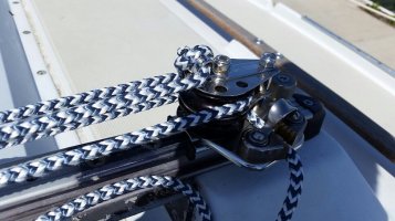
4. Utilized Lewmar rope clutches due to feedback from several area racers, plus the price is on-par if not cheaper than several competitive products and I was able to take advantage of a friend's marine store discount. The way they operate as compared with a cam clutch is really impressive and does appear to both reduce line wear and allows easy release of the line under just about any load (and this one I can confirm). I've also found they can be 'feathered' fairly well to loosen things just slightly if needed (halyard tension, etc). Being an engineer I found them fairly nifty as compared with other clutches.

Ok, now onto the nitty-gritty:

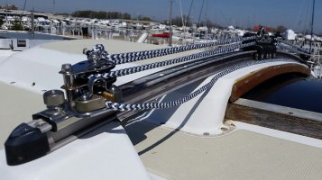
First, I laid-out all of the deck hardware with lines running through them and various volunteers (chiefly my dad and myself) holding hardware while keeping lines taught in order to ensure proper routing, cut half-angles with lines for the deck organizers, ensure straight shots into the rope clutches and the best average wrap over a winch (since some lines will be angled over to be able to be winched in). I just used a sharpie to mark the deck since at some point the deck will be painted, just not yet (also, my deck is so chalky even the permanent marker was removed with the first washing):
Here's is the deck organizer:
IMG_20170724_202823.jpg

Here's the new main-sheet winch:
IMG_20170724_202809.jpg

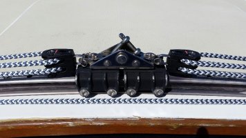
Also included were a bank of 5 rope clutches on the Port side for:
1. Main Halyard (8-10mm)
2. Port Spin Halyard (8-10mm)
3. Center Jib Halyard (8-10mm)
4. Topping Lift (6-8mm)
5. Downhaul (6-8mm)

Technically this is a gang of 3 directly next to a gang of 2, due to differing line diameters as indicated above in parentheses.

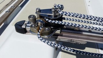
On the Starboard side I marked out for a bank of 3 rope clutches for:
1. Starboard Spin Halyard
2. Boom Vang
3. Cunningham

As mentioned in the cliff-notes version above, I ensured all lines ran freely and that the half-angles of the lines leading through the deck organizers averaged out. I also used all ball-bearing sheaves and torlon balls with any of the halyard sheaves (as recommended by Garhauer due to loading).
 
Last edited:
Top