Installing a dedicated starter battery

Sven

Seglare
Yes there are two parts.

The fuse
<snip>

and fuse holder (available in both a double and single)

<snip>

They can also be used off a buss bar which makes them very handy

<snip>

In your excellent battery cable tutorial you make the point that the power lugs have to be sized for the posts. It looks like the fuses only come with 3/8" post holes ? Those holes would be too big for 1/4" and 5/16" posts. So do you install a properly sized power lug on a cable and then to a bus with 3/8" posts ? It might not be an issue for us as we might have the right size posts but I am curious.

Thanks,


-Sven
 

mherrcat

Contributing Partner
Based on the buss bar picture, I take it that if the house bank takes a dump you operate the windlass manually?
 

Maine Sail

Member III
Maine Sail - Two questions on your bus layout, assuming it is an actual boat in the photo.

Yes actual boat, an SC-31

1) How is the battery switch lead connected? I don't see a lug.

The lug is upside down under the fuse buss bar. This allows you to come in fused and go out to the switch on the same buss bar post.

2) What does the fuse on the house bank lead protect?

It protects the house bank wiring to comply with ABYC standards and is within about 9", wire length, of the POS battery post. Sometimes the 7" rule is just impossible to comply with. The box did not have the height to accommodate the MRBF on top of the battery post so I installed it on the buss bar.. If there is any short between the switch and the battery, which on this boat is quite a distance, that fuse will blow.
 

Maine Sail

Member III
In your excellent battery cable tutorial you make the point that the power lugs have to be sized for the posts. It looks like the fuses only come with 3/8" post holes ? Those holes would be too big for 1/4" and 5/16" posts. So do you install a properly sized power lug on a cable and then to a bus with 3/8" posts ? It might not be an issue for us as we might have the right size posts but I am curious.

Thanks,


-Sven

Yes I always size my battery lugs to posts properly. I have been round and round with the guys at Blue Sea on this and they refuse to make a 5/16" MRBF. They insist that one size difference is fine. Personally I think it is SLOPPY, but it is what it is, until they offer an MRBF in 5/16". I don't use MRBF's on 1/4" posts but will use them on 5/16" as the fusing is safer than not and likely a lot safer than the 1 size difference...

I try and use 3/8" buss bars when I can and an owner is not on a "tight" budget...
 

Maine Sail

Member III
Based on the buss bar picture, I take it that if the house bank takes a dump you operate the windlass manually?

If that 275A house bank fuse took a dump you'd have more issues than a windlass not working...:) The windlass is fused at 125A per the manufacturers recommendation despite it being on 2/0 wire. They don't want it to stall and burn up. With a fuse rated for the wire in that situation you could easily burn up the motor before the fuse blew. If the windlass could take a 275A fuse then I could have simply used the house bank fuse to protect it and the wire. The wire is sized to avoid to much voltage drop but the windlass fuse is sized to protect the motor per the manufacturers request...
 

mherrcat

Contributing Partner
I admit I am somewhat electrically-challenged, but it looks like everything on that buss is connected to the house bank. If for some reason the house bank was depleted or failed it seems the windlass would not work, unless there is a switch somewhere downstream that allows it to be switched to another power source.
 

Sven

Seglare
Yes I always size my battery lugs to posts properly. I have been round and round with the guys at Blue Sea on this and they refuse to make a 5/16" MRBF. They insist that one size difference is fine. Personally I think it is SLOPPY, but it is what it is, until they offer an MRBF in 5/16". I don't use MRBF's on 1/4" posts but will use them on 5/16" as the fusing is safer than not and likely a lot safer than the 1 size difference...

I try and use 3/8" buss bars when I can and an owner is not on a "tight" budget...

I just measured the bolts on the Lifeline batteries and the negative is 5/16" while the positive is 3/8".

Is that standard or is there some special reason why they might have done that ?

Once again; thanks to one and all for the informative Q&A, it is very useful.


-Sven

(PS Mainsail, I did tell them you sent me and then had to admit that I didn't know who Mainsail is in real life :egrin:)
 

Maine Sail

Member III
I just measured the bolts on the Lifeline batteries and the negative is 5/16" while the positive is 3/8".

Is that standard or is there some special reason why they might have done that ?

Once again; thanks to one and all for the informative Q&A, it is very useful.


-Sven

(PS Mainsail, I did tell them you sent me and then had to admit that I didn't know who Mainsail is in real life :egrin:)

Just tell Mike that RC at Compass Marine sent you.. 3/8 POS and 5/16" NEG is pretty standard but many companies such as Trojan often use 5/16" and 5/16"...
 

Sven

Seglare
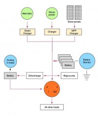
My current layout plan

After all of the discussion this is what my current plan looks like. Assume that the lines all represent the positive voltage and that each item also has an appropriate ground connection. The automatic bilge pump and the eco-charger are both hard wired always connected. All other loads means everything but the auto bilge pump and the eco-charger.

The arrow direction just shows energy flow direction (charge-discharge).

I was amazed how many things I had wrong until I finally did the diagram and had to think it out. I'm not very good with EasyDraw so the diagram is a bit crude but still keeps me honest (?).

EDIT: I've now put the Battery Monitor on the negative post but I have not yet dug out the documentation so this is probably still incorrect per Mainsail's comments.


Screen shot 2011-10-22 at 8.35.10 AM.jpg


-Sven
 
Last edited:

Maine Sail

Member III
Sven,

If you're going to use an Echo Charger all charge sources should be led to the house bank, not the switch. That's just how they work.
 

Sven

Seglare
Sven,

If you're going to use an Echo Charger all charge sources should be led to the house bank, not the switch. That's just how they work.

But if I do that how does the back-up battery get charged if the main bank dies or shorts out ?

I also don't see how that would work with the battery monitor ?

Maybe my drawing just isn't showing what I think it is showing.


-Sven
 

Maine Sail

Member III
But if I do that how does the back-up battery get charged if the main bank dies or shorts out ?

fi that rare situation were to occur just flip to BOTH after taking the neg lead off the house bank. The problem is that the Echo is a one way device and is intended to have all charging sources led directly to the house bank. If you were to flip your bank switch to the start bank then the house bank would get no charge at all.

I also don't see how that would work with the battery monitor ?

It does not affect the battery monitor if it is wired properly

Maybe my drawing just isn't showing what I think it is showing.

The battery monitor monitors in/out of the house bank, and the Echo takes from it, thus the neg lead for the Echo, bilge pump and every other load or source needs to be on the load side of the battery shunt. NOTHING other than the BATT side of the shunt should connect to the NEG battery post of the house bank not even the reserve battery.
 

Sven

Seglare
The battery monitor monitors in/out of the house bank, and the Echo takes from it, thus the neg lead for the Echo, bilge pump and every other load or source needs to be on the load side of the battery shunt. NOTHING other than the BATT side of the shunt should connect to the NEG battery post of the house bank not even the reserve battery.

Let me think about that for a bit. What you say above sounds like exactly what I was trying to draw so I suspect my drawing is just misleading. I did assume the battery monitor was hooked on the positive side so maybe that's where the confusion starts from. I need to pull out the Echo charge installation manual.

But like a said, let me think about it to see if the cobwebs get cleared up. Thanks for keeping me on my toes :)


-Sven
 

Loren Beach

O34 - Portland, OR
Senior Moderator
Blogs Author
"Old" battery technology

This thread has very ancient roots!
http://en.wikipedia.org/wiki/Baghdad_Battery

Admittedly, I have no idea if any ancient mariners were using a 1-2-all switch, however..............
:)

Stu,
In those olden days, a "Catalina 34" would have been known (in Cubits!) as a Catalina 20. The Lateen sail would have looked rather cool, also. :nerd:

LB
:devil:

ps: this post originally composed in digital Cuneiform, on clay.
 
Last edited:

Maine Sail

Member III
Let me think about that for a bit. What you say above sounds like exactly what I was trying to draw so I suspect my drawing is just misleading. I did assume the battery monitor was hooked on the positive side so maybe that's where the confusion starts from. I need to pull out the Echo charge installation manual.

But like a said, let me think about it to see if the cobwebs get cleared up. Thanks for keeping me on my toes :)


-Sven

Sven,

You won't find much in the Xantrex Echo Charger manual as it is a "leftover" from the Heart Interface days and basically unchanged other than the Xantrex logo. It is completely lacking based on how it is most widely used today. it is in dire need of corrections, updated wiring diagrams and omissions about its operation completely left out.

Myself and a couple of other electrical guys in the industry have been after Xantrex for a long while to correct many misleading or flat out incorrect statements and/or omissions from that manual dating back well over 6 years. Sadly I have had to charge a number of customers for diagnostics only to tell them their device is working as it should but the manual was misleading or incorrect or simply left out information that should have been there. I have also had to correct numerous wiring mistakes because the manual lacks sufficient information for many DIY's to wind up properly wiring the device.

I have sent Mariana, Xantrex head of tech support, and her predecessor, detailed instructions of what would be helpful additions and corrections four times now. They freely admit this is an issue, and they field calls frequently, but they are Xantrex so need we say more..:mad: They have all this in email form not just from me but a couple other guys who are as frustrated as I am. it is UNFAIR to the consumer that this manual is so badly written but they could give a rat's ass.. They have made promise after promise that this would get corrected but after six years I doubt were going to see any changes. Add to that that half their tech support guys don't even know how the device operates, and you have one real mess. Xantrex never designed this product so they have apparently put little time and effort into it..

What you will find is one drawing showing a charger hooked to the house battery and the Echo in-between. That charger drawing should also include wind, solar and alternator. This is how Heart originally thought this device would be best used, with their chargers. FF 15+ years and it has been more widely used with solar, wind, alternator as well as shore chargers. Yet it still lacks drawings showing and including wiring diagrams for these devices.

The Echo is a great device with a horse sh*t manual..:rolleyes::mad:

Sorry for the rant!!
 

Stu Jackson

C34IA Secretary

Just that when you do a wiring diagram you show the points of connection, not the positions of a switch. That's all.

That's why I provided you with a few samples. Hope they help.

In Maine Sail's sketch, Option 2 in my link, he shows the posts AND the Both position. But notice how carefully he shows where the wires do land on the switch. Your sketch seems a bit unclear on that.

In Option 1, Dave neglected to show the C post.

clj1950's diagram shows 1 and 2 but neglects to show the C post.

It's not an uncommon mistake, see? :)
 
Last edited:

Sven

Seglare
Stu,

Just that when you do a wiring diagram you show the points of connection, not the positions of a switch. That's all.

I think you misread the diagram, that is an icon for a 0-1-1&2-2 switch, nothing else.

That's why I provided you with a few samples. Hope they help.

They actually show what I'm trying to get away from. KISS is what I am after with this whole exercise.

Thanks,


-Sven
 
Top