• Untitled Document

    Join us on April 26th, 7pm EST

    for the CBEC Virtual Meeting

    All EYO members and followers are welcome to join the fun and get to know the guest speaker!

    See the link below for login credentials and join us!

    April Meeting Info

    (dismiss this notice by hitting 'X', upper right)

Battery Monitors

Tom Metzger

Sustaining Partner
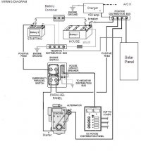
Loren - The shunt MUST be inserted into the 1/0 black wire between the house bank and the engine ground point (at least it's 1/0 on the E-34, E-32, and E-35-3). If the house and start batteries use the same negative wire going to the engine ground point then the shunt has to be placed so only the house bank current goes through it. In other words, you may have to rewire the negative connections on the two banks to accomplish this.

The attached sketch, which was drawn for a different purpose, shows where the shunt has to be wired in for either battery if they have a common negative connection to the engine. Most likely, it would be easiest to eliminate the jumper between the batteries and run a separate wire from the disconnected battery to the engine.

The engine power (starter, glow plugs, pump, blower, and instruments) does not go through the #4 wire to the distribution panel. It comes off the battery switch.

I hope this helps.
 

Attachments

  • charger and battery diagram A.pdf
    42.6 KB · Views: 103
Last edited:

CaptnNero

Accelerant
Timely Typing Tom

Tom,

Thanks for the clarification. I have an XBM unit that I was about to install. I started making some drawings of existing cabling and what I needed to make it work. Now I've got your clear cut directions to lean on.

Tom Metzger said:
Loren - The shunt MUST be inserted into the 1/0 black wire between the ...
 

vbenn

Member III
Link

When I acquired E380 #22 last year, it was equipped with a Link 10, and a Heart Inverter. The inverter is great and I expect to use it more frequently now that we have a new house battery bank of 4 Mastervolt AGMs under the starboard settee. It took awhile before I began to understand the Link. It's a useful monitor for the house bank, but is not giving me accurate data on AMPs because the start battery is also connected via the selector switch. The Link 10 is intended as a one bank monitor. A separate Link product is available to monitor 2 banks.

Vince Benn
Wild Blue
 

stuartm80127

Member II
Link20

I just rewired from the batteries to the engine, installed a Link-20 and a dual circuit plus switch from Blue-Sea on my E27. Now have a starting plus house circuit. I run a small inverter but didn't feel compelled to add in a switch for it by buying a link 2000.


I chose the Link-20 to monitor each battery because on a previous Boat I installed a Link-10 and was very pleased with it's monitoring of my batteries though the setup process took a little getting used to. The switch quality of the Link-20 doesn't seem as nice as the link-10. Best to epoxy the cable sheathing to the back of the link-20 so that you don't accidentally pull any wires from the connector. I bought some high quality cat-5 network cable (four pairs), tinned the ends and used that to run about 20 feet between my batteries and where it is mounted near the switch panel.

Stuart
 

wurzner

Member III
I have an older Heart Inverter EMS 1800 Charger/Inverter 1800 Watt/65 AMP charger. It is a very old modified sine wave that is about the size of a shoe box, but a little thinner and perhaps sligtly wider. My batteries are old (2000) and per Guy's thread about batteries, would most likely be in great shape still but they went dry while the boat was up for sale. I added water and did 2 equalization cycles (the EMS 1800 has that feature) and they lasted for my 16 day trip no problem. I have a cruising equipment AMP-Hour +2 monitor which I believe heart acquired and turned into their link 20 system. It shows voltage for both banks, amperage being drawn, charging voltage and amperage per bank/both banks, and remaing battery capacity. I don't use the remaining battery capacity at all since I don't know what my actual Ah capacity is given the old batteries. Using battery voltage and Ah consumption, you can pretty much figure out when to charge or change banks. Having he equalization capability is great though. I would have purchased 4 6V batteries if the equalization charge didn't bring them back a little. To do a crude acid test like Loren, I used the microwave to see the hysterisis on the batteries and they were fine for the trip as mentioned...even ran my wifes 1500 watt hair dryer one day. I would typically never do that without running the engine, but was curious to see what the inverter could handle. In principal (historically), I agree with Rob about a true sign wave. After seeing how it worked on my microwave though, I would NEVER go with a true sine wave now since the microwave performance was great! Microwaves performance deteriorates significantly (read a factor of 2~3X) if they do not get a could sign wave. I must say, my old invertor must have a good modified sign wave since I didnt' notice it. The difference being about 3~4 times the size and weight. None the less, true sine waves are more efficient and than likely reliable since they are basically big wire windings with much less electronics.

Good thread and just thought I'd add my .01 cents to it. Either way, I love the inverter and the Ah monitoring capabilities. Also, my norcold draws between 3.8 and 4.5 Ah as a comparision to Loren's...looks like about the same power requirements.

Shaun
 

rwthomas1

Sustaining Partner
Shaun,
The main reason I would prefer a true sine wave inverter is supposedly flat panel monitors and laptop screens work better with them. IIRC, I read that in Calders book. I would like to add a flat panel TV in future and also laptop navigation so I want to make sure they work as intended. The true sine wave inverters are not that much more money. RT
 

CaptnNero

Accelerant
good for the money

Shaun,
The main reason I would prefer a true sine wave inverter is supposedly flat panel monitors and laptop screens work better with them. IIRC, I read that in Calders book. I would like to add a flat panel TV in future and also laptop navigation so I want to make sure they work as intended. The true sine wave inverters are not that much more money. RT

While I disagree on the money part, I do agree that the pure sine wave inverter is the way to go. You can expect to pay about twice as much for a PSW versus an MSW inverter. For longevity the MSW isn't good for motors. Plus the some of the electronics don't handle the MSW well.
 

wurzner

Member III
I agree that sine if the better choice. I was only saying that my small modified sine wave has been really good to me. If I had to buy one, I'd probably go true sine if the money was close. Our laptop and everything else works fine on the one I have though which is contrary to what I would have expected. Please let the list know what you end up getting and what it costs.

regards
shaun
 

rwthomas1

Sustaining Partner
Yes, you are correct, true sine wave is more money. For reference here are prices from Jackrabbit: www.jrenergy.com

Freedom Marine 20
Weight: 45 lbs
Dimensions: length: 13.2" x width: 11.5" x height: 7.9"
List Price: $1,200.00
JR Price: $840.00

Prosine 2.0 Inverter/Charger
Weight: 24 lbs
Dimensions: length: 5.7" x width: 11.2" x height: 17.7"
List Price: $1,700.00
JR Price: $1,190.00

An additional $350 gets you true sine wave performance. If I have done the math correctly thats about 30% more expensive than MSW. As most of us know, $350 is pocket change in the boat world. Especially since anyone considering a 2000watt inverter is likely to be installing it in a pretty substantial sailboat. A small price to pay for making sure pricey electronics work correctly. Like the blender for instance....... YRMV, RT
 
Last edited:

CaptnNero

Accelerant
inverters without chargers

...If I have done the math correctly thats about 30% more expensive than MSW. ...

Rob, that's some good pricing you quoted from jrenergy. When I was saying twice as much for the PSW vs MSW, I wasn't talking about buying a charger too as in the products that you quoted. When you look at just inverter products without chargers, the price multiplier that I spoke of becomes obvious. I don't think jrenergy carries those.

If you've already got a good charger, it would be too bad to have to toss it to put an inverter in, so that cost needs to be factored in also.

We must deal with such trade-offs to keep our blenders happy . ;)
 

Loren Beach

O34 - Portland, OR
Senior Moderator
Blogs Author
Better Amp-Hour meter results

I recently got the new shunt properly wired (at least I hope so) and thought I would post a small diagram of the result. The only real change from factory stock is, of course, at the common ground point on the port side of the back of the engine -- flat flange on the bell housing. Now all the Neg. current does indeed return to the house bank through the shunt. All the LED's on the e-meter are now green... :rolleyes:

This is mostly a drawing of the "big wires" -- although I did include a reference to the sensing wires from the shunt and the original voltage sense wires that go the panel. I left out the Battery charger, if anyone wonders.

The only section of wire that might yet get replaced is the 18 inch connector from the "load side" of the shunt to the engine ground. It is about a #2, and smaller than the others. The factory used #4 to go to and from the panel, and one of these days I do intend to upgrade these by one size.
But that's another project! :p

The layout you see is geographically close to accurate for my boat. The starting/emergency Optima battery I added is under the aft berth, to the rear of the engine. The House bank, consisting of two golf carts batteries, is directly in front of the engine under the steps.

If I still do not have it right, it could be because I messed up in expressing myself in my drawing application, or I am simply suffering from brain fade.
:nerd:

Cheers,
Loren in PDX
Olson 34 Fresh Air
 

Attachments

  • O-34 Big Wires.pdf
    20.2 KB · Views: 135
Last edited:

Tom Metzger

Sustaining Partner
Well done.

Loren - Congratulations!

I didn't see a copyright notice on your sketch, but I decided not to make a copy, just in case. :)

Replacing 18" of #2 wire will do nothing for you. A very rough calculation indicates that you will save about 8 millivolts at 70 amps, assuming the connector drops are the same. Better to buy a couple of beers with the saved money.

FWIW, I used #2 for all of my replaced battery connections and for the starter battery. I suspect that the engine only draws about 60 amps when the starter is running.
 

Loren Beach

O34 - Portland, OR
Senior Moderator
Blogs Author
Pictures and Switches, oh my...

Feel free to copy it, but I am not sure my little drawing would help anyone else, mostly because it was laid out (in a general way) to the physical location of the parts in our model of boat. I relate a lot better to that style of illustration than to a straight "block diagram."
:nerd:
Next phase is to replace the stock 1-2-All switch with the model 8080 Blue Seas distribution panel. I now have that panel mounted in a teak frame to fit over the hole that will be left when I remove the old switch.

If anyone has any comments about this changeover, please do pass them along. I sometimes do miss the obvious when launching into these projects...
;)

It looks like the cables just need to be shifted from the existing switch to the new panel...

Cheers,
Loren in PDX
 

Attachments

  • 163233.jpg
    163233.jpg
    15.1 KB · Views: 222

Shadowfax

Member III
Loren,

Why did you feel the need to replace the 1 2 All switch with the Blue Sea unit? The Blue Sea unit is much more sexy, but did the stock switch fail in some way? Mine is working fine
 

Loren Beach

O34 - Portland, OR
Senior Moderator
Blogs Author
Switching the "switch"

As usual, my experiences probably can serve equally as a warning to avoid... or an example to emulate. :)
After we put in the refrigeration, we wanted to keep the master switch for the then-designated House Bank energized all the time so that the drinks would always be cold when we got to the boat. Also, I was feeling a bit guilty for not having the bilge pump circuit energized when we were gone.
Problem is that with the master switch "on" the engine could be started when we are not there.
(Realistically, it is so easy to break into and hotwire a typical boat that the whole concepts of "locks" is almost mirth-provoking.) :rolleyes:

So I put a hidden cutoff switch for the engine panel. This works OK, but in the long run there is always the concern that someday a person might rotate the 1-2-all switch to off when under power and ruin a diode.
We also converted over to a dedicated starting/emergency battery, and no longer need or want to switch back and forth between two banks.
In 20 years we have never yet left the switch on "both" and run two banks down... but lots of people around us have.

Long story shorter: it seems like time to change over the original master switch to one with an "engine circuit" separate from the house power supply that can be left on all the time. This also puts a big breaker on the house hot side very close to the battery bank, always a good thing to show a future surveyor, IMHO.

And, Almost forgot: we have no keyed start switch on the cockpit panel. Just a replacement manual switch instead. First owner put it in, and I am inclined to stick with it, having been on a multitude of boats over the decades with keys that were frozen in place, broken off, lost! -- and other inconvenient problems. :mad:

So, I want the engine panel outside in the cockpit to be cold unless the inside master switch is turned on.

The Blue Seas panel is rather sexy looking also, as you noticed...
:cool:

Loren
 
Last edited:

CaptnNero

Accelerant
...And, Almost forgot: we have no keyed start switch on the cockpit panel. Just a replacement manual switch instead. First owner put it in, and I am inclined to stick with it, having been on a multitude of boats over the decades with keys that were frozen in place, broken off, lost! -- and other inconvenient problems. :mad:

So, I want the engine panel outside in the cockpit to be cold unless the inside master switch is turned on.

The Blue Seas panel is rather sexy looking also, as you noticed...
:cool:

Loren

Loren, I like this idea about the non-keyed switch outside. I recently picked up a similar Blue Seas panel but it includes a pair of bilge pump breakers also. I liked that the bilge pump breakers can only be reset, not manually turned off.

I do wonder what kind of manual switch that is that you don't have to worry about breaking it off like a key ? While I never leave the key in while under sail, I don't like the idea of having to insert it whenever we transition back to power.

Several years ago there was a couple sailing the Chesapeake in a small boat (26ft Catalina) in the middle of a calm summer night. While crossing the shipping channel they realized that a tanker was bearing down on them and they were becalmed. When one of them reached down in the dark to start the engine it was hopeless since they key was broken off. They had to abandon ship and swim away before the tanker hit them. They were picked up healthy miles away the next morning and reunited with their vessel which had drifted into a marina on the opposite side of the Bay with minor damage. They were on their way again that afternoon. As for the tanker, it ran aground after trying to avoid their abandoned vessel, but fortunately it was mild enough that there was not a spill.
 
Last edited:

Captron

Member III
Blue Seas Switch

Loren,

I rewired my battery bank using the same switch you pictured. My rewiring was extensive however so I can't say if yours will be a simple change out. I removed two on-off-both battery switches, a charge control rheostat, two isolators, and a diesel genset. Then I upgraded all of the wires, added a solar panel, heavy duty alternator, 3 stage regulator, 150 amp main breaker, inverter, and a combiner to charge the start battery. I did retain the Xantrex 40 amp shore power charger and I installed a shunt and a Xantrex TM500 battery monitor. I love Xantrex products and their customer service is pretty good too.

Everything works as planned and the switch makes things real simple. The engine switch cuts off the starter, the house switch manages everything else except the inverter and bilge pumps. There's nothing to remember ... on is on and off is off, period.

The next stage will be to rewire the main panels ... there's still a rat's nest back there despite all of the rewiring, simplifying and straightening out that I've done back there. Maybe next year. I just have to remember that time is nature's way of keeping everything from happening at once ... or as my wife says "patience dear, patience".

My wiring diagram is attached
 

Attachments

  • Wiring Diagram.JPG
    Wiring Diagram.JPG
    40.7 KB · Views: 106

Loren Beach

O34 - Portland, OR
Senior Moderator
Blogs Author
Nice work!

Ron,
Beautiful diagram!
Are you a CAD-experienced person, perchance?
:D

Thanks again, and when I get smart enough to figure out a reasonably intelligent question to ask, I'll write to you!

Best,
Loren in PDX
Olson 34 Fresh Air
 
Top