Battery Monitors

Captron

Member III
Diagram

Thanks for the compliment ... Nope, no CAD experience ... just Paint and PowerPoint ... I tend to copy someone else's work and modify it to suit my needs ... I think this was originally a Blue Seas diagram.

You'd be amazed at the drawings that you can turn out with PowerPoint ... sometimes you can just overlap shapes then take it over to Paint or some similar tool and erase or fill in something ... then bring it back as an object ... it's then easy to add dimension arrows and other annotations ... works for me anyway. At least I think it's easier than a pencil and T-Square.
:nerd:
 

ted_reshetiloff

Contributing Partner
That is exacty how I have my electrical system set up including the Blue Seas panel. The only difference is I dont have the Solar Panel. Its been working great, but I ultimately want to upgrade my house bank, get my alternator rebuilt or replaced, and possibly add a small inverter to run a better coffee pot and or a small flat panel tv. Ron I need to do the same panel rewire. Thinking about taking it on this winter but.... Its really the end game for my electrical system as I have done all the other upgrades you mentioned. Curious to know how big your house bank is, and where it is located? I am guessing its under the aft cabin bunk as your 38 is an earlier model than mine.
 
Last edited:

cawinter

Member III
Battery sense wires observation

A note to Loren (and others): The sensing wires in your diagram are not fused ANYWHERE , and they are permanently connected to the batteries. If the insulation ever chafes (or is someone plays with the meters behind the panel...:boohoo: ) they are a potential disaster waiting to happen. I had my little adventure with the charger cables a few weeks ago, and from now on everything will be fused.
Just a thought.
 

Tom Metzger

Sustaining Partner
As I remember, the Link 10 cable comes with in-line fuses for the battery connections. If you make up cables you should definitely include fuses, both for ABYC compliance and common sense.
 

Loren Beach

O34 - Portland, OR
Senior Moderator
Blogs Author
Right, Tom.
The small sense wires from the pos. battery terminal to the monitor did require a fuse installed, and both were installed.
Note that the ones from the shunt in the Neg. half are not fused, and are not required to be in their instructions.

But, now that this has been brought up, it looks like the two factory red wires from each battery over to the DC panel switch and analog meter both do need fuses.. They are about a #14 or 12, as I dimly remember.

It's always something...

:)

Loren
 

cawinter

Member III
Those are the ones...

Yep, those are the ones. They are always hot, regardless of switch setting! So be carefull when you poke around the breaker panel and think that everything is dead with the battery switch to OFF...

I am not quite sure what I'll do with the sense wire. One thought is to just sense on the starting battery (w/ a separate off switch instead of the toggle) and have the house battery looked at by the LINK10. It was interesting to see that the LINK10 still pulls about 28mA even when it is off, amounting to somewhere around 4-5Ah/week.
 

Captron

Member III
Batteries

That is exacty how I have my electrical system set up including the Blue Seas panel. The only difference is I dont have the Solar Panel. Its been working great, but I ultimately want to upgrade my house bank, get my alternator rebuilt or replaced, and possibly add a small inverter to run a better coffee pot and or a small flat panel tv. Ron I need to do the same panel rewire. Thinking about taking it on this winter but.... Its really the end game for my electrical system as I have done all the other upgrades you mentioned. Curious to know how big your house bank is, and where it is located? I am guessing its under the aft cabin bunk as your 38 is an earlier model than mine.

Yes ,my batteries are under the front edge of the quarter berth, behind the nav sation seat and in front of the fuel tank bulkhead. I have two group 31 gel cells and a group 24 gel cell starting battery shoehorned in there. I often think that I want more battery capacity but then I'm not sure it's worth the remodeling. The gel cells give me fast charging rates, no maintenance, and good capacity for their size. Next time I'll consider AGMs just because they give a few more amp hours for the G31 size case.

We typically cruise the Bahamas from December through May and so far this set up works fine. We run about 40 to 50 amp hour deficits (net after solar input) on a typical day and run our engine about an hour to an hour and a half each day to recover that. Normal sailing days often include at least that much motoring anyway. Bigger batteries wouldn't change that much. Our biggest power hog is the fridge which is on all the time followed by the Lectra-san unit ... probably eating less would save us amps as well as pounds.

We installed a Xantrex 1800 watt inverter this summer. (we put it under the nav station seat) We'll see how that goes. It has a built in transfer switch and we have it wired to the main AC panel so all of our outlets are live when it's on. We have a microwave where the oven should be and the inverter will run it provided the engine's running. We don't expect to use it much ... mostly it stores pots and pans. We've learned to get by without an oven over the years ... just heats up the cabin too much anyway.

The inverter mainly supplies power for various chargers, the computer ... and a small flat screen TV that when wired to the computer also plays DVDs but it's also useful for power tools like my Dremel or a corded drill. I make my coffee by boiling water in a teapot on the stove then pouring it through a Melitta filter directly into my mug. The wife uses the same hot water for her tea. Works for us.

We've thought about blenders, breadmakers, and coffee makers but we really can't give space away for such single use tools. Generally things on our boat have to serve more than one purpose or be particularly useful.

I'd be interested in what you end up doing for your panel wiring project, I'll be taking that one on next season I expect.

:egrin:
 

Tom Metzger

Sustaining Partner
Link 10 drain

It was interesting to see that the LINK10 still pulls about 28mA even when it is off, amounting to somewhere around 4-5Ah/week.
Chris - 5 ah is peanuts. If you are going to leave your boat for a couple of months that's 45 ah; still not a problem.

Is there something I'm not seeing?

If concerned. pull the fuses.
 

CaptnNero

Accelerant
self-discharge

...It was interesting to see that the LINK10 still pulls about 28mA even when it is off, amounting to somewhere around 4-5Ah/week.
Chris, for perspective that is on the order of the self-discharge rate for conventional flooded cells.
 

joerun26

Member II
Link 20 Battery Monitor Question

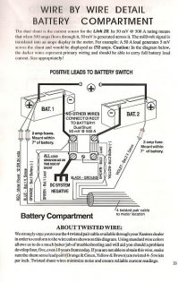
I recently got the new shunt properly wired (at least I hope so) and thought I would post a small diagram of the result. The only real change from factory stock is, of course, at the common ground point on the port side of the back of the engine -- flat flange on the bell housing. Now all the Neg. current does indeed return to the house bank through the shunt. All the LED's on the e-meter are now green... :rolleyes:

I'm in the process of installing a Link 20 Battery Monitor and would appreciate any input from those who have one installed. I wired per the instructions, and the meter doesn't indicate a current draw correctly on one bank but does on the other. Whe I talked to Xantrex today and after an hours worth of checks, they concluded I have a ground problem. I also seem to be sharing load between the batteries even when my starting battery disconnect switch is open. For those of you with a XAntrex 20, is your "engine ground" from the shunt essentially connected to the starting battery negative ? (similar to Loren's drawing) I know troubleshooting like this is very difficult, - I would appreciate any dwings of a 2 battery bank system. ITs possible I'm not properly grounded ...
 

joerun26

Member II
Link 20 Installation

Joerun26 - How about my sketch on this thread from 7-26? Two batteries and two shunts.

Tom -
Thanks for the response. Did you purchase an additional shunt or is it drawn to show how its electrically connected ? (the link 20 shunt is set up for 2 banks). Other than that, did you run your batery negatives through the shunt before going to the engine as ground? (I believe I just paralleled my negatives to the shunt but didn't alter the original routing to ground ) Sounds like the problem ?
Thanks alot,,
joe
.....
 

Tom Metzger

Sustaining Partner
Monitor wiring

Sounds like the problem ?
Ah, the light slowly dawns. :cool:

The monitor only knows what goes through the shunt. If you have both negatives connected to the same shunt it will read the combined currents. My sketch shows the way you MUST set it up. Two shunts. Pay close attention to how the charger is wired to the batteries. The monitor will not tell you the information you want to know if it is not done exactly this way.

I didn't show the alternator connections, but they must be the same as the charger with the current flowing through the shunt to the battery. This is a no brainer, as the alternator ground is normally connected to the engine ground. It is good practice to run a heavy wire from the alternator ground to the engine ground connection. It should be the same as you are using for the battery connections; usually #2 or larger.

Don't quit until both monitors work correctly. You will like the results.

Good luck.
 

Loren Beach

O34 - Portland, OR
Senior Moderator
Blogs Author
Proper Shunting

Ah, the light slowly dawns. :cool:

The monitor only knows what goes through the shunt. Good luck.

<snip>

This sounds like the problem I created when I initially got my ground shunt wired incorrectly. In retrospect the flaw seems obvious...
:rolleyes:

Best,
Loren
 
Last edited:

Howard Keiper

Moderator
What a delicious thread! I just read and tried to digest all of it over my morning coffee...wow.
I don't make a living at this kind of thing, having retired, but if I did, I'd look at this kind of dialog as pure, practical source material. I am ABYC (electrical) certified; NMEA (cmet) too...AND an Ericson sailor...and am most proud of that.
Thank you all for a great discussion.
howard keiper
SeaQuest E-35 II
Berkeley
 

joerun26

Member II
Link 20 Wiring

Thanks Tom,

Makes sense . I'll make sure I route each battery negative through the shunt BEOFRE going to the engine ground. Regarding 2 shunts.. take a look at that attached image - doesn't the link 20 shunt provide the seperation you're talking about ? If not...... where did you get the second shunt ?

Thanks again,
joe
 

Attachments

  • Link 20.jpg
    Link 20.jpg
    63.1 KB · Views: 78

Tom Metzger

Sustaining Partner
Good job Xantrex

Yes, that is a "dual shunt", or two shunts on a common mounting plate. Their diagram is the same as mine. They must be quick learners. :egrin:

This means that if your connections of the battery heavy wires is correct you should concentrate on the small wires that are probably mis connected at one end or the other.
 
Last edited:

joerun26

Member II
Link 20 Wiring

Great -

Thanks alot Tom for the quick replys.. I'll let you know how it turns out.

Joe
"Tenacious"
 
Battery bank on E29

Well, 2 months away from getting our E29 down here. I was up working on it this past weekend. The PO had two "marine" batteries as the house/starter banks. Has anyone installed the Xantrax charger/inverter on an E29? If so, with what kind of battery bank? I would love to go this route to have the inverter and no brainer charging of the bank under engine power or shore power and have the automatic switching from shore to inverter on the AC distribution panel.

Any suggestions???
 

Tom Metzger

Sustaining Partner
A suggestion

Any suggestions???
Yes, don't let the inverter kill your batteries when the shore power goes off and you are out of town on business for a week It happens to lots of people.
 
Top