Guest viewing is limited
- You have a limited number of page views remaining
- 24 guest views remaining
- Register now to remove this limitation
-
Untitled Document Join us on March 28th, 7pm EDT
for the CBEC Virtual Meeting
EY.o March Zoom Meeting
All EYO members and followers are welcome to join the fun and get to know the people you've met online!
See the link below for login credentials and join us!
(dismiss this notice by hitting 'X', upper right)
You are using an out of date browser. It may not display this or other websites correctly.
You should upgrade or use an alternative browser.
You should upgrade or use an alternative browser.
Coolant Conundrum
- Thread starter Prairie Schooner
- Start date
Interesting diagrams, but confusing.
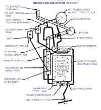
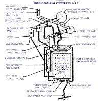
Note that this diagram:
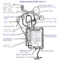 and this diagram:
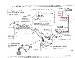
are different. I think both are a bit misleading.
The first one shows both the exhaust manifold AND the accumulation tank (what I had been calling the expansion tank) venting to the (plastic) overflow tank. While this makes sense, I don't believe the accumulation tank Ericson used was fitted with such an overflow vent (I know mine wasn't). So, in most setups, only the engine exhaust manifold vents to the overflow tank, unlike what the diagram shows.
The second photo confusingly calls the (plastic) overflow tank the expansion tank (not to be confused with the accumulation tank). And oddly, this diagram labeled "Water Heater Hook Up...." omits the accumulation tank altogether. Confusing!
Remember, the (plastic) overflow tank is always un-pressurized. The top cap has a hole in it that vents the tank to atmosphere. This allows the tank to fill and empty itself of coolant that escapes from the pressurized caps of the manifold (and/or the accumulation tank).
The accumulation tank, like the manifold, is pressurized once the coolant heats up, and thus, requires a sealed, pressurized cap (like a radiator cap on your car).
Note that this diagram:
 and this diagram:
are different. I think both are a bit misleading.
The first one shows both the exhaust manifold AND the accumulation tank (what I had been calling the expansion tank) venting to the (plastic) overflow tank. While this makes sense, I don't believe the accumulation tank Ericson used was fitted with such an overflow vent (I know mine wasn't). So, in most setups, only the engine exhaust manifold vents to the overflow tank, unlike what the diagram shows.
The second photo confusingly calls the (plastic) overflow tank the expansion tank (not to be confused with the accumulation tank). And oddly, this diagram labeled "Water Heater Hook Up...." omits the accumulation tank altogether. Confusing!
Remember, the (plastic) overflow tank is always un-pressurized. The top cap has a hole in it that vents the tank to atmosphere. This allows the tank to fill and empty itself of coolant that escapes from the pressurized caps of the manifold (and/or the accumulation tank).
The accumulation tank, like the manifold, is pressurized once the coolant heats up, and thus, requires a sealed, pressurized cap (like a radiator cap on your car).
Last edited:
Jeff,
Re housekeeping of threads in Post #20:
We do have a master thread on engine overheating: https://ericsonyachts.org/ie/threads/dreaded-universal-5432-running-hot-syndrome-master-thread.3713/
But this thread is sorta specific, so I'll just link to it there.
In my opinion your eventual complete cooling system upgrade story ought to also be a separate thread, or perhaps a blog entry (which mine was).
Seems like there are several ways to accomplish the same task. Not to dilute  the discussion, but on my boat, which used to have a water heater connected between the freshwater pump and thermostat, some enterprising craftsman built a custom heat exchanger out of copper tubing and old fire equipment fittings. This is installed above the manifold level. I think this also serves as an “expansion” tank. The manifold coolant expansion hose was capped off. Now you fill the system from the top of the heat exchanger (I use a giant syringe and tubing). I recently relocated the overflow tank to the top of the lazarette so it would more properly drain and vent.
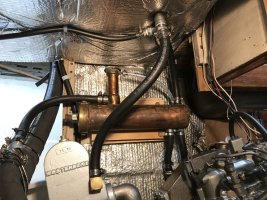
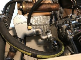


General note: the cap on the coolant tank has a pressure rating, and has to be right one. They fail over the years and are sometimes replaced incorrectly by previous owners. Worth checking and replacing if old and questionable.
Frank Langer
1984 Ericson 30+, Nanaimo, BC
Ken,Interesting diagrams, but confusing.
Note that this diagram:
View attachment 51402 and this diagram: View attachment 51404
are different. I think both are a bit misleading.
The first one shows both the exhaust manifold AND the accumulation tank (what I had been calling the expansion tank) venting to the (plastic) overflow tank. While this makes sense, I don't believe the accumulation tank Ericson used was fitted with such an overflow vent (I know mine wasn't). So, in most setups, only the engine exhaust manifold vents to the overflow tank, unlike what the diagram shows.
The second photo confusingly calls the (plastic) overflow tank the expansion tank (not to be confused with the accumulation tank). And oddly, this diagram labeled "Water Heater Hook Up...." omits the accumulation tank altogether. Confusing!
Remember, the (plastic) overflow tank is always un-pressurized. The top cap has a hole in it that vents the tank to atmosphere. This allows the tank to fill and empty itself of coolant that escapes from the pressurized caps of the manifold (and/or the accumulation tank).
The accumulation tank, like the manifold, is pressurized once the coolant heats up, and thus, requires a sealed, pressurized cap (like a radiator cap on your car).
The metal accumulation/expansion tank on our E30+ does have an overflow vent hose to the plastic tank.
Frank
Ok, good to know. Does the exhaust/coolant manifold vent to the overflow as well, or just the accumulation tank?Ken,
The metal accumulation/expansion tank on our E30+ does have an overflow vent hose to the plastic tank.
Frank
Prairie Schooner
Jeff & Donna, E35-3 purchased 7/21
Interesting diagrams, but confusing.
Note that this diagram:
View attachment 51402 and this diagram: View attachment 51404
are different. I think both are a bit misleading.
The first one shows both the exhaust manifold AND the accumulation tank (what I had been calling the expansion tank) venting to the (plastic) overflow tank. While this makes sense, I don't believe the accumulation tank Ericson used was fitted with such an overflow vent (I know mine wasn't). So, in most setups, only the engine exhaust manifold vents to the overflow tank, unlike what the diagram shows.
The second photo confusingly calls the (plastic) overflow tank the expansion tank (not to be confused with the accumulation tank). And oddly, this diagram labeled "Water Heater Hook Up...." omits the accumulation tank altogether. Confusing!
Remember, the (plastic) overflow tank is always un-pressurized. The top cap has a hole in it that vents the tank to atmosphere. This allows the tank to fill and empty itself of coolant that escapes from the pressurized caps of the manifold (and/or the accumulation tank).
The accumulation tank, like the manifold, is pressurized once the coolant heats up, and thus, requires a sealed, pressurized cap (like a radiator cap on your car).
You're ahead of me, Ken. I'm still trying to figure out what it says, and am only just beginning to determine if it's right. Working on the boat today, I couldn't find anything in the circuit that looked like an accumulator/expansion tank. The PO put in a new water heater and perhaps they removed it. Or, maybe our boat never had one. We also don't have the valve (#8) between the riser and the 'lift can', whatever it's called.
Based on Doug's input, here is updated labeling. #05 has got to be the manifold reservoir but I can't figure out what the original Ericson label is.
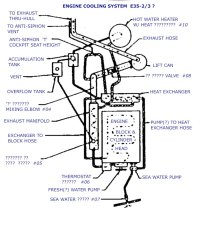
Is "lift can" what I've been calling a muffler? What does it lift?
The water lift muffler pushes the mixture of hot water and exhaust gases uphill from a point below the engine, thru a higher loop of hose, and downward to the transom exit fitting.Is "lift can" what I've been calling a muffler? What does it lift?
Frank Langer
1984 Ericson 30+, Nanaimo, BC
Just the accumulator tank.Ok, good to know. Does the exhaust/coolant manifold vent to the overflow as well, or just the accumulation tank?
Note also that the "anti syphon T" for the exhaust system water was kind of an EY precaution and not used by all other customers of Universal diesels. I noticed that the install manual for our new Betamarine said such an addition was optional, dependent on the position of the water lift muffler vs the height of the elbow at the exhaust manifold. Our installer measured the relative heights and said we did not need this extra hose.
(Just an added data point to slightly cloud up the clarity of the discussion... )
I left the old anti syphon hose off the new engine exhaust system and glassed in the little hole in the transom, just above the exhaust fitting.
Edit: note the position of the overflow plastic tank in photo #3 in this blog entry: https://ericsonyachts.org/ie/ubs/wiring-engine-detail-part-2.677/
The overflow tank is not pressurized and the cap vents to atmosphere. The former/factory location had the horizontal location of this tank just about in the same plane compared to the pressure cap on the former Universal diesel engine. I do believe the horizontal position of the overflow tank is important relative to the hose exit from the pressure cap, tho.
Last edited:
My apologies, guys. I was talking from memory only about a system I last worked on in 2017, and I got some of it wrong....
The stock Ericson accumulation tank does have an overflow hose that vents to the (plastic) overflow tank. In my setup (Universal M25), the exhaust/coolant manifold also has an overflow hose to the (plastic) overflow tank. That makes this diagram correct for my boat:
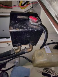
Here's the accumulation tank:
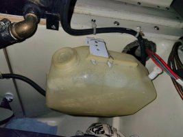
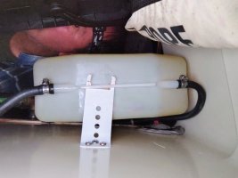
And here's the overflow tank with two ports on the bottom:
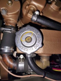
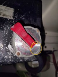
Maybe one of the keys to understanding the accumulation tank setup is this: The pressure cap on my accumulation tank is 7lbs, while the cap on the manifold is 14 lbs. So, under normal circumstances, the accumulation tank will always be the one venting to the overflow tank. The overflow vent on the manifold, then, is redundant, except in cases where the engine doesn't have a water heater with an accumulation tank installed
The stock Ericson accumulation tank does have an overflow hose that vents to the (plastic) overflow tank. In my setup (Universal M25), the exhaust/coolant manifold also has an overflow hose to the (plastic) overflow tank. That makes this diagram correct for my boat:

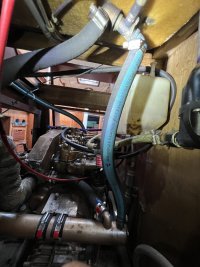
Here's the accumulation tank:

And here's the overflow tank with two ports on the bottom:


Maybe one of the keys to understanding the accumulation tank setup is this: The pressure cap on my accumulation tank is 7lbs, while the cap on the manifold is 14 lbs. So, under normal circumstances, the accumulation tank will always be the one venting to the overflow tank. The overflow vent on the manifold, then, is redundant, except in cases where the engine doesn't have a water heater with an accumulation tank installed


Attachments
Last edited:
Prairie Schooner
Jeff & Donna, E35-3 purchased 7/21
Thanks Ken. We definitely don't have a tank like that. And our plastic overflow tank has the two outlets molded in but one was never cut open. Based on that it's probably safe to say our boat never had the expansion tank. I'm tempted to think they're kind of like an appendix, though Loren's observations on the 'T' could offer reasoning for why some boats have them. Further down the rabbit hole.My apologies, guys. I was talking from memory only about a system I last worked on in 2017, and I got some of it wrong....
The stock Ericson accumulation tank does have an overflow hose that vents to the (plastic) overflow tank. In my setup (Universal M25), the exhaust/coolant manifold also has an overflow hose to the (plastic) overflow tank. That makes this diagram correct for my boat:
View attachment 51412
Here's the accumulation tank:
View attachment 51416
And here's the overflow tank with two ports on the bottom:
View attachment 51417 View attachment 51421
Maybe one of the keys to understanding the accumulation tank setup is this: The pressure cap on my accumulation tank is 7lbs, while the cap on the manifold is 14 lbs. So, under normal circumstances, the accumulation tank will always be the one venting to the overflow tank. The overflow vent on the manifold, then, is redundant, except in cases where the engine doesn't have a water heater with an accumulation tank installed
View attachment 51420 View attachment 51423
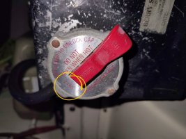
Interesting. The stock manifold tank cap on the 5432 is "Radiator Cap, Pressurized 7# PSI."
With the additional tank, I guess that gets moved up to 14 PSI. But only then?
With the additional tank, I guess that gets moved up to 14 PSI. But only then?
Prairie Schooner
Jeff & Donna, E35-3 purchased 7/21

Exhaust Riser to Muffler, E35-3
Leak in hose connecting exhaust riser to muffler. Universal M-25 in 1986 Ericson 35-3.youtube.com
You're right Christian, the hose is shot. Shame on me for not catching it sooner. We did have a mechanic remount the engine in July of 2022 and replace the manifold/riser pipe in September of that year. They didn't call out this hose then, though it must have been in rough shape. Sigh. But could this account for the loss of coolant or it getting diluted?
View attachment 51364 View attachment 51365
You've got me curious about the staining from the exhaust. I'm going to track down some older photos of that area to see how the current state compares to previous years.
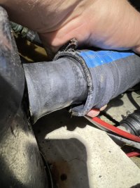
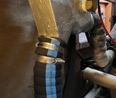
The hose between riser and muffler looks fairly new*, but there are slices in it between each set of hose clamps. I can't figure out what would have caused those. In addition to the slices, there's a mismatch at the muffler. The exit fitting on the riser is 1.99" OD. The input of the lift muffler has an OD of 1.71" and that's with some rubber hose on it to increase diameter. The output of the muffler is 1.65". The hose ID is 2.00".
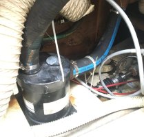
* I found a photo from 2021, when we got the boat. The mechanic definitely installed a different hose in 2022, which has ribs in it. I also note leak staining at the base of the muffler even back then. The new hose is pretty soft.
old- SHIELDS ??X II Marine Wet Exhaust Water SAE J200?R2 250 2000 2" 51 MM 2008
new- SHIELDSAUST - C Marine Wet Exhaust/Water SAE J2006R2 Lloyds 11/00001 252-2000 2" 51MM 2021
Is there a better way to connect a 2" hose to 1.65" diameter nipple than slipping some hose on it?
What's the reason for corrugated tubing? The best I could find on the interweb was it bends into curves easier. I wonder if it's more prone to splitting.
Prairie Schooner
Jeff & Donna, E35-3 purchased 7/21
Prairie Schooner
Jeff & Donna, E35-3 purchased 7/21
Good catch! Now that you point it out, it's obvious. But it totally slipped by me. The nipple on the muffler is kind of short so that's what happened there, too. One mystery solved. Thanks, Christian.It does look like the second hose clamp on several hoses was tightened outside the stub. That would certainly ruin a hose. Both clamps are supposed to be on the stub.
View attachment 51436

