• Untitled Document

    The 2024-2025 Fund Raising Season has Opened!

    EricsonYachts.org has opened the season for raising funds to support the expenses of the site. If you would like to participate, please see the link below for additional information.

    Thanks so much for your continued support of EricsonYachts.org!

    2024-2025 Fund Raising Info

Coolant Conundrum

Prairie Schooner

Jeff & Donna, E35-3 purchased 7/21
How to Flush Cooling System Without Starting Engine?

It's clear that salt water has been getting into the coolant circuit. A small leak could be the reason I could never keep fluid in the overflow tank. The overheat that precipitated this work might have enlarged a small preexisting leak between chambers of the exchanger. At the beginning of this season I cleaned the HX with Barnacle Buster and didn't notice anything, but could easily have missed a smaller version of it. It makes me think that a pressure check of the HX might be a good maintenance item every couple years.

coolant 2024_10-29 post overheat sm.jpeg

At any rate, I'm going to do a thorough coolant circuit flush. My current plans are to use Barnacle Buster. Since I don't want to start the engine on the stands, I'm thinking of using a spare bilge pump in a bucket of BB to circulate the flush, with several repeats, maybe changing flow directions, described in the youtube below. Have any of you had luck with the pump technique? I'd take out the thermostat. Would I have to bypass the coolant pump somehow?

pump method

These are a few other references on flushing which make the most sense to me. There is some contradictory advice, Natch.


Christian Williams

E381 - Los Angeles
Senior Moderator
Blogs Author
That makes sense to me, although I would leave the solution in the system overnight before pumping it out. I suppose circulation for several hours, as he did, is logical, but dissolving scale and such seems to me more a matter of allowing time for the descaling to work. Anyhow, worth a try.
 

Kenneth K

1985 32-3, Puget Sound
Blogs Author
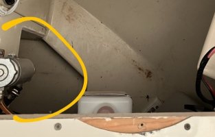
I copied the photo below from @peaman in post #27 of this thread:
IMG_0129~4.jpeg

I find that tank on the left to be intriguing. I wonder if it's an accumulation tank like we talked about earlier in this post.

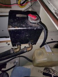
It's a lot less clunky than my tank:
IMG_20241101_213109568_AE.jpg

@peaman , do you have any info about that tank? Thanks.
 

peaman

Sustaining Member
do you have any info about that tank? Thanks.
I bought the boat in March of 2021. The engine has marks on it suggesting that the engine was installed in June, 2020. It is a Universal M-25 XPB.

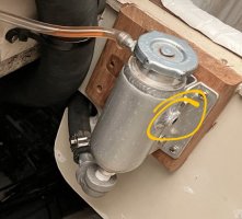
The conventional coolant cap on top of the engine is wired closed and hand marked with "DO NOT OPEN". The tank which you circled is the fill point for coolant, and the cap is about 18" above the "conventional coolant cap" on top of the engine. There is a single (1/2"?) hose from the engine to the bottom of the upper tank. The upper tank has a cap which is rated for maybe 7 psi? When that pressure is exceeded, coolant should overflow into the adjacent unpressured plastic tank which is just visible at bottom center in the photo. When the engine cools, causing the pressure to drop, some amount of coolant should flow by suction back from the plastic tank to the other high tank.

I don't know the correct terminology for the various parts, but I think the unpressured plastic tank is commonly called a coolant recovery tank. I believe the purpose of the elevated pressure tank is to assure that the engine cooling system is always fully flooded at any heel angle.

I expect to be at the boat (again!) tomorrow, so if you have any questions, let me know. If I remember, I'll shoot some photos.

Edit to add:
Since you might be thinking of replacing your clunky tank...
The tank which came with the boat was a good couple of inches taller than the one I have now. It was obstructing the trash receptacle just forward of the tank, so I decided to replace it. It took some searching, but I finally found a suitable aluminum tank from a source which caters to race car enthusiasts (can't recall which). They call it an "overflow tank".
 
Last edited:

Loren Beach

O34 - Portland, OR
Senior Moderator
Blogs Author
Solely in the interest of avoiding a move towards any unwarranted conclusion nowadays, I wonder if EY decided early on that the observed raised coolant tank found on many (most?) of the Universal diesel installs in the 80's Ericson's was something (chosen in discussion with Universal) Universal engineers requested regarding their installations?
This raised the production cost some, so they must have thought they had good reason to do so.

Having viewed the engine position in same-era Ericson 33RH, E-32-3, and Ericson 34 models I cannot recall any obvious difference in engine mounting within the boat that would require any extra higher/raised coolant overflow tank.

The install manual for our very-similar (Kubota) Betamarine 25 mentions choosing to add or not to add the 1/4" syphon break hose to the exhaust like the Ericson's all have (and so did our Olson 34 from the EY factory) but the Betamarine manual mentions nothing (zero) about adding any raised coolant container. It would be helpful to know if this coolant tank was installed in any of the thousands of Catalina boats the used the M25 and M25XP models, for instance.

There might indeed be some good reason to keep those little tanks, but I do wish someone with some maritime engineering backgound could weigh in and explain the nuances for me. I wonder what problem they thought they needed to solve.

I do know that the coolant level in my overflow tank (previous and current engine) is supposed to be at or a bit above the cap on the engine coolant add-point.
 
Last edited:

Kenneth K

1985 32-3, Puget Sound
Blogs Author
expect to be at the boat (again!) tomorrow, so if you have any questions, let me know. If I remember, I'll shoot some photos.
Yeah, if you could shoot a couple photos of it, and find out who the manufacturer is I'd be interested.

There may be some differences though, my clunker tank has two pressurized hoses (plus the overflow hose), so coolant flows through it just like the flow through the manifold and a water heater itself.
 

peaman

Sustaining Member
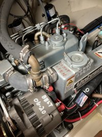
Top of engine:
IMG_0133.jpeg
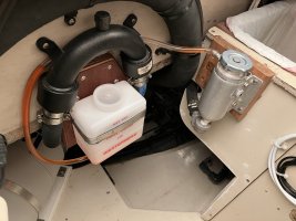
The coolant cap is rated for 13 psi, compared to the higher tank at 7 psi. The hose coming off of the bronze elbow is connected at the bottom of the aluminum tank.

IMG_0134.jpeg
There is no identifying information on the tank. I used only aluminum fittings for the aluminum tank, including nipple, elbow, hose barb, and overflow barb fitting, all from McMaster Carr, as I recall.
 

Kenneth K

1985 32-3, Puget Sound
Blogs Author
That's a really clean install. Do you remember where you got the aluminum tank? Also, is there another fitting on the right that might allow it to be a flow-through tank?
IMG_0134~2.jpeg

By the time coolant gets pushed into the overflow (recovery) hose, it's pretty hot. Are you sure that clear plastic hose is rated for heat?
 

peaman

Sustaining Member
Are you sure that clear plastic hose is rated for heat?
In the present configuration, there is no flow-through, so the tank does not get very warm at all, so the clear vinyl tube is safe. The tank assures that the engine block is always flooded for best cooling, and the only fluid which rises to the aluminum tank is that which is displaced from the much hotter engine block due to thermal expansion.

As you pointed out, there is a threaded opening (as we say in the trade) on the upper right side of the aluminum tank, but it is smaller (3/8"?) than the fitting at the bottom. But I don't see a need for having circulation through a remote tank in a closed circuit system like the common fresh water/coolant systems most of our boats have.
 

Kenneth K

1985 32-3, Puget Sound
Blogs Author
In the present configuration, there is no flow-through, so the tank does not get very warm at all, so the clear vinyl tube is safe.
Yeah, good point. That seems like a better setup than my (larger) tank with two hoses, flow-through, and heated coolant circulating through the tank. Seems like mine adds a lot more coolant to the system and more pressurized hoses & fittings for no added benefit.
 

peaman

Sustaining Member
I'm curious as to where your two hoses connect at the engine. It may be very straightforward to convert to a static system like mine.
 

Kenneth K

1985 32-3, Puget Sound
Blogs Author
It's just like the diagram Jeff posted in post #53. Water goes from the heat exchanger to the accumulation tank to the water heater then back to the engine.

Yeah, I think it would be pretty easy to convert. Just add a Tee to the high point of another hose, and then a single line to the tank. Would probably eliminate about 4 ft of hose.
 

Loren Beach

O34 - Portland, OR
Senior Moderator
Blogs Author
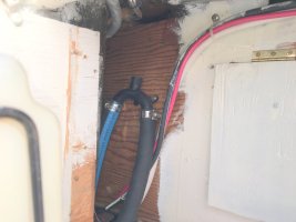
Pardon my ignorance, but there is a "vented loop" shown in the larger photo in reply 67. What's it for? Nothing like that was ever installed in our engine compartment.

Also, as we used to say in my sports car/autocross days: That's one Sanitary engine compartment!! :cool:
 

Kenneth K

1985 32-3, Puget Sound
Blogs Author
There might indeed be some good reason to keep those little tanks, but I do wish someone with some maritime engineering background could weigh in and explain the nuances for me. I wonder what problem they thought they needed to solve.
After reading all these posts and seeing some of the different configurations out there, I think the purpose of the "accumulation" tank finally became clear to me.

It's pretty simple: The coolant fill cap must be the highest point in the system. If not, you can't fill those parts of the system that are higher than the cap (you can't pour uphill). Thus, you'll always have air trapped somewhere in the system, which risks overheating.

The Universal Motors Owner's Manual (from 1985, I assume) says this:

"The manifold serves as the engine expansion tank to allow for expansion of coolant as it is heated. You also fill the system at this point. In some cases when hot water heaters are installed an expansion or surge tank may be required to prevent air from entering the system."

So, when the engine leaves the factory, the coolant cap on the manifold IS the highest point in the system and the manifold itself has some "accumulation" capacity. All is good (and though they don't mention the overflow recovery tank, we all understand how those work). The engine manufacturer doesn't know whether the final installation will or won't include a water heater, what model of heater it will be, or what the final geometry of heater-vs-engine placement will look like. All the manufacturer can say is that some installations might require an additional expansion/accumulation/surge tank.

But, if any part of your boat's "add-on" coolant system rises higher than the engine's original filler cap, a secondary tank provides:
1) a filler cap at the highest point in the system, and
2) a high-point where any air trapped in the system can bubble up to the top of the tank so it's not re-circulated through the system.

My $.02 anyway....
 

Prairie Schooner

Jeff & Donna, E35-3 purchased 7/21
Pardon my ignorance, but there is a "vented loop" shown in the larger photo in reply 67. What's it for? Nothing like that was ever installed in our engine compartment.

Also, as we used to say in my sports car/autocross days: That's one Sanitary engine compartment!! :cool:

Is that the same thing as an anti-siphon loop?


In this thread Nick, Ken and some others have an extended conversation that includes information around hose routing, loops, sizes. I'm still working my way through all that's in there, but it includes information about vented loops.

Ken, how has your thinking about these systems developed in the past four years? Solidified? Changed?
 

Christian Williams

E381 - Los Angeles
Senior Moderator
Blogs Author
I think that's a good explanation from Ken. On both my Ericsons the water heater was well below the level of the manifold, so the cap there was the highest point. No additional gear required except a plastic coolant overflow tank.

When I rerouted my water heater hoses from the heat exchanger to the thermostat ports, one hose became higher than the manifold cap. I put a bleed valve at that point.
 

Loren Beach

O34 - Portland, OR
Senior Moderator
Blogs Author
I think that's a good explanation from Ken. On both my Ericsons the water heater was well below the level of the manifold, so the cap there was the highest point. No additional gear required except a plastic coolant overflow tank.

When I rerouted my water heater hoses from the heat exchanger to the thermostat ports, one hose became higher than the manifold cap. I put a bleed valve at that point.
Good points. I recall that when I replaced the factory hot water tank many years ago, the new location I chose was even a little lower in the hull than the aft lazaret factory location.
Without understanding why, I somehow had done the right thing. :)
 

Loren Beach

O34 - Portland, OR
Senior Moderator
Blogs Author
But, if any part of your boat's "add-on" coolant system rises higher than the engine's original filler cap, a secondary tank provides:
1) a filler cap at the highest point in the system, and
2) a high-point where any air trapped in the system can bubble up to the top of the tank so it's not re-circulated through the system.
Ah so! This must be where the "duck comes down" ! :D
 

Christian Williams

E381 - Los Angeles
Senior Moderator
Blogs Author
Regarding the vented loop:

On my boat, "the Oberdorfer directs raw water to the heat exchanger. It circulates there, absorbing heat from the engine coolant, then exits to an anti-siphon valve tucked high above the waterline. From there the raw water descends to enter the exhaust elbow on the engine."

My loop is cockpit high, taking advantage of a space over the engine bay behind the aft cabin bulkhead.

antisiphon loop .jPG
 

peaman

Sustaining Member
there is a "vented loop" shown in the larger photo in reply 67. What's it for?
A 1" hose is connected at the engine heat exchanger raw water outlet, it rises to the vented loop, before dropping down to the inlet at the wet exhaust. So @Christian Williams has it correct. Whether or not the vented loop is necessary is another question.

I find it interesting that this thread goes into details on the plumbing of both the raw water and the "fresh water" coolant systems, two very different systems hydraulically, but occupying the same space and both equally important and demanding.


That's one Sanitary engine compartment!! :cool:
Thanks for this very satisfying compliment. I worked several years as yacht captain or engineer, so I strive for a high standard (no judgement!). I was very lucky to find a very lightly used boat, and in my three years' ownership, I have done lots of work, to the extent that I can identify 6 different projects in that image alone, and at least three others opposite the camera's view.
 
Top