• Untitled Document

    The 2024-2025 Fund Raising Season has Opened!

    EricsonYachts.org has opened the season for raising funds to support the expenses of the site. If you would like to participate, please see the link below for additional information.

    Thanks so much for your continued support of EricsonYachts.org!

    2024-2025 Fund Raising Info

Coolant Conundrum

Kenneth K

1985 32-3, Puget Sound
Blogs Author
Ken, how has your thinking about these systems developed in the past four years? Solidified? Changed?
Most of what I know about exhaust systems in general came from this excellent article:


Like the article says, many of the recommended practices described just aren't possible in small sailboats. Then, compromises have to be made. Ultimately, there's no ONE right way to skin the cat.
 

Prairie Schooner

Jeff & Donna, E35-3 purchased 7/21
Thanks Ken. I'll dive into that.

In the meantime, on further research, I think I should use a descaler instead of Barnacle Buster, which is geared more for removing mineral deposits from salt water and organic life, ie, the raw water system. Trac's Descaler is designed for a "closed loop cooling system".

This video includes a casual interview with the former owner of the company that developed Barnacle Buster. His comments are more informative than the website. There's a lot of content in the video which is too-cute fluff for my interest. The following sections were the most informative for me.
3:45-7:30 - Intro flush device, BB explained
17:00-18:30 - Device in operation
Barnacle Buster Engine Cooling Therapy
 

nquigley

Sustaining Member
My apologies, guys. I was talking from memory only about a system I last worked on in 2017, and I got some of it wrong....

The stock Ericson accumulation tank does have an overflow hose that vents to the (plastic) overflow tank. In my setup (Universal M25), the exhaust/coolant manifold also has an overflow hose to the (plastic) overflow tank. That makes this diagram correct for my boat:
View attachment 51412

Here's the accumulation tank:
View attachment 51416
And here's the overflow tank with two ports on the bottom:
View attachment 51417 View attachment 51421

Maybe one of the keys to understanding the accumulation tank setup is this: The pressure cap on my accumulation tank is 7lbs, while the cap on the manifold is 14 lbs. So, under normal circumstances, the accumulation tank will always be the one venting to the overflow tank. The overflow vent on the manifold, then, is redundant, except in cases where the engine doesn't have a water heater with an accumulation tank installed
View attachment 51420 View attachment 51423
I removed my water heater yesterday. According to the M25 manual, I could have connected the engine’s coolant outflow hose directly to the HX and dispense with the accumulator tank that the heater used (the highest point in the circuit, which keeps air out of the system), but I decided to keep the accumulator tank as a convenient place to monitor (and top up) the coolant level. So the engine-out line now goes up to the accumulator (used to go to the heater) and the outflow from that tank goes to the HX.
 

nquigley

Sustaining Member
The overflow hoses beside the pressure caps on my engine coolant manifold and on my accumulation tank simply drain down to the bilges - no plastic holds by tanks. I seldom need to top up the coolant level, so I guess I’m not sending much overflow coolant to the bilges
 

Frank Langer

1984 Ericson 30+, Nanaimo, BC
The overflow hoses beside the pressure caps on my engine coolant manifold and on my accumulation tank simply drain down to the bilges - no plastic holds by tanks. I seldom need to top up the coolant level, so I guess I’m not sending much overflow coolant to the bilges
On our E30+ the accumulator tank has a small house that drains into the plastic hold tank, and it has a hose that drains into a fitting just below the main rad cap on the engine. It works well like this, and no coolant into the bilge.
Frank
 

Christian Williams

E381 - Los Angeles
Senior Moderator
Blogs Author
I remain confused by fact that neither of my engines, M25 or 5432, has/had a separate expansion tank. They do have a plastic overflow tank connected to the manifold tank cap.

Are we defining expansion tank and accumulator tank the same? Are we calling the tank integral to the engine the manifold tank? I call the plastic tank a coolant overflow tank, yes? Don't all "accumulator" tanks have an air bladder within?

Sorry but the Kubota diagrams I consulted for such basic questions were not helpful.
 
Last edited:

Loren Beach

O34 - Portland, OR
Senior Moderator
Blogs Author
Are we defining expansion tank and accumulator tank the same? Are we calling the tank integral to the engine the manifold tank?
My understanding of this is that EY was concerned about having the highest point in the sealed coolant system always be above all the other components like hoses or the external hot water heater coil. Perhaps (?) Mr. King was being cautious about these components' relative heights given the need to raise some of the HW Tanks higher due to the narrowing of the stern sections of his designs? (Just guessing ....)
 

peaman

Sustaining Member
Are we defining expansion tank and accumulator tank the same? Are we calling the tank integral to the engine the manifold tank? I call the plastic tank a coolant overflow tank, yes? Don't all "accumulator" tanks have an air bladder within?
I have seen the plastic tank called a reservoir, recovery tank, expansion tank or overflow tank. The manifold tank is integral to the engine. I don't know what the proper name for the elevated pressure tank is. As for an air bladder, there should not be one in a radiator system.

For better insight on what the expansion/overflow tank is for, I found a short Youtube video that explains how the pressure cap works. Water expands a lot when heated, and if a radiator is filled to the top, it will either build high pressure, or will overflow. The special design of the pressure cap allows coolant to be released to the overflow tank before pressure becomes excessive, and it then allows that coolant to return to the system, through a vacuum valve in the pressure cap, when the system cools down. I believe that the only reasons for a separate pressure tank is 1) to make sure that the rest of the system, including a water heater coil for example, is flooded at all times, or 2) to provide a more convenient fill point in the case of poor access to the manifold tank. If both of those are satisfied, the manifold tank and the plastic tank should be enough.

Radiator Pressure Cap
 

Prairie Schooner

Jeff & Donna, E35-3 purchased 7/21
I remain confused by fact that neither of my engines, M25 or 5432, has/had a separate expansion tank. They do have a plastic overflow tank connected to the manifold tank cap.

Are we defining expansion tank and accumulator tank the same? Are we calling the tank integral to the engine the manifold tank? I call the plastic tank a coolant overflow tank, yes? Don't all "accumulator" tanks have an air bladder within?

Sorry but the Kubota diagrams I consulted for such basic questions were not helpful.

Christian, could you, Sean, and Loren declare by Royal Fiat that henceforth and evermore on EYo the reservoir integral with the exhaust be called Manifold Coolant Tank, the plastic one will be referred to as Overflow Tank, and the metal one as (?Expansion/Accumulation?) Tank? Our factory manual calls it an Accumulation Tank.

I found these two helpful resources:
Though I don't think this article addresses a system with both an expansion and an overflow tank. It seems that if you have both, with caps, that the manifold cap would release at a higher pressure, as someone described here earlier.


One thing that is stressed in both of these is that the expansion tank should be the highest point in the system.

Our M25 does not have an expansion tank and I haven't seen evidence yet that one existed in the past. The best idea I've heard thus far is that its inclusion has something to do with the kind of water heater installed and its location.
 

Christian Williams

E381 - Los Angeles
Senior Moderator
Blogs Author
HW Tanks higher due to the narrowing of the stern sections of his designs?

I thought Loren's theory made sense. But then Vim, a 32-3, has an accumulator tank, and on that model the water heater typically sits much lower than the manifold cap.

Raritan Kuuma pano.JPG

And Jeff, in terms of world domination, the Royal Fiat of moderators here is more like a Royal Yugo.
 

Prairie Schooner

Jeff & Donna, E35-3 purchased 7/21
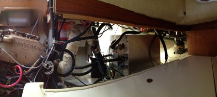
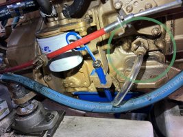
With some guidance from Ken I found the block coolant drain, on the starboard side of the engine. It was impossible to see from aft and difficult from forward. Contrary to valve conventions, it is open when the handle is perpendicular to the direction of flow. I added the vinyl tube for current work.
2024_11-20_M25 drain sm.jpeg

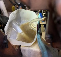
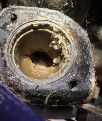
It was difficult to move the lever, but it yielded to gentle taps on a wooden drift pin. The remaining liquid that drained was pretty funky, further evidence that raw water was getting mixed into the coolant, perhaps replacing most of it.
2024_11-20_M25 drained sm.jpeg


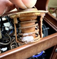
This is the crud I found when I removed the thermostat. I've got it home for testing.
2024_11-20_M25 thermostat sm.jpeg . 2024_11-20_M25 thermostat socket sm.jpeg

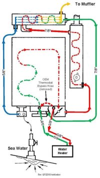
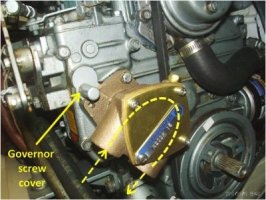
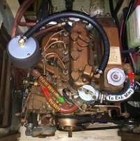
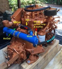
The almost universally described way to flush the coolant circuit involves running the engine. I'm starting to wonder if my plan to do it by external pump will work. Knowing the direction of coolant flow would be critical and that was a puzzle until I found this resource:


The post is by KWKloeber in the Catalina 30 Wiki. I decided to copy the images to this thread in case that link goes bad at some future date. But I give full credit to the original author.

M-25_coolant flow 1 C30wiki.jpg
M-25_coolant flow 2 C30wiki.jpg
M-25_coolant flow 3 C30wiki.jpg
M-25_coolant flow 4 C30wiki.jpg

The page also has flow diagrams for the M35 if that's your jam.
 

Loren Beach

O34 - Portland, OR
Senior Moderator
Blogs Author
Good diagram. Thanks Jeff.
I believe that the yellow hose labeled "To Muffler" is where my original M25XP had a T fitting at the top of the engine bay, with a 1/4" hose going back to a little outlet on the transom just above the exhaust fitting (that 'peed' out a small stream all the time the engine was running) .
 

Prairie Schooner

Jeff & Donna, E35-3 purchased 7/21
Good diagram. Thanks Jeff.
I believe that the yellow hose labeled "To Muffler" is where my original M25XP had a T fitting at the top of the engine bay, with a 1/4" hose going back to a little outlet on the transom just above the exhaust fitting (that 'peed' out a small stream all the time the engine was running) .
Yes, Loren, on our boat there's an anti-siphon device which can be seen in the second image of post #38. The video below includes an explanation of AS-Valve vs T-With-Hose that was good enough for me. Apparently either is acceptable. And, I learned the correct way to pronounce Vetus. Though I'm going to stick with my way of saying diaphragm.

This is another device I'm going to remove, test, and maybe replace. Whether it's a spring or duckbill valve, I doubt it's been looked at in at least a decade. I've never examined it in our three years. Maybe I should move it to a location a little easier to access.
 

Christian Williams

E381 - Los Angeles
Senior Moderator
Blogs Author

American English pronunciation is often what we say it is. Hence my personal pronunciation of clevis pin.

I was once asked by a foreign English student how to pronounce Carradine, the surname of the family of actors. Dine or deen? I said you have to ask them, there's no rule. So I did ask David. He laughed and said "both are fine."
 
Top