e-39 Rudder Design

Shamwari

Please Contact Admin.
I'm trying to make a really good 3D drawing of an e-39 modified rudder and researching what makes a rudder work well in the conditions we experience with this boat.
I plan to make a new rudder for my boat this spring and want to have the foam blanks cut on a CNC machine before I take it out of the water. To do this I need a very accurate drawing of the outside shape - the inside I will do by hand when I strip the old rudder.

The problem is that I have been getting a lot of information on what makes a rudder work at the speeds we experience. It seems that a fairly safe way to go is to base it on a NACA 4 series airfoil ( think old slow aircraft wings).

I want to extend it about 2.5 inches down in the hope that this will bring some rudder surface into the area where it will be more influenced by the propwash.
I also want to extend the back rearward about 4.5 inches.

However I have some questions and I thought some people may have some experience that would be helpful.

Should I go deeper than 2.5" - I understand that depth is more important than width ( think longer wing)

What is the strange flatter area at the top of the rudder on an e-39 for. (It may be that because it is behind the aft edge of the keel that it is only a section of trailing edge)

I am planning to make the curve on the front of the rudder like an extension of the origional rudder but make the very bottom flat in a scaled down shape of the NACA 4 profile. This will make it a little stronger and I think it will keep it providing "lift" better.

I am also planning to make the aft edge of the rudder flat rather than tapering it to a near sharp edge. It is stronger and the square edge might help with trailing vortices ( it does with Kamm back cars).

I know this is more technical than we usually get, but i'm hoping someone has been through this process and will have some insight into what actually works well and what doesn't.

I will send the drawings into the sight after I'm finished so anyone can use them if they wish to.

John Gleadle
 

Mark F

Contributing Partner
Blogs Author
Hi John,

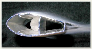
I don't know if it would be the same effect but the manufacturer (Seedwings) of the hang glider that I fly designed a streamlined tubing that has a flat trailing edge and a very low drag coefficient. Here is a photo of a wind-tunnel test.
 

Attachments

  • streamlined-sensor-tubing.jpg
    streamlined-sensor-tubing.jpg
    35.3 KB · Views: 855

Walt Lawrence

Member I
e 39 rudder info

Hi

Just some input on the rudder discussion. I procured original drawings for the original design specs on my 39's rudder. The as built design reduced the as drawn design by app. 27 % to get the boat in line with the the IOR requirements of the era.

All that said, the drawnings I have give full size airfoil shapes and measurements to accomplish what some friends of mine did..they built the rudder to the as drawn design.

Sarayu still wants to back down with difficulty, but it is somewhat improved since the modification. The other side of the results is that she handles with much improved response in forward...and considering that she spends most of her time in that direction I feel that it was money well spent. :egrin:

I would say that there was app. 2 - 3 inchs added to the depth of the rudder just from what I remember off the top of my head.

I would be most interested to hear what you are able to come up with as far as a new design. Contact me back channel if I can help with your project..you also might consider contacting Guy Stevens of Aiki for some input.

Fair seas,
Walt Lawrence
Sarayu E-39
 

Martin King

Sustaining Member
Blogs Author
E39 rudder mods

Been there and done that. I had Foss Foam build an extended rudder
keeping the same NACA wing section and profile. You want to go
deeper, not wider to get the increased blade area down where it will
do some good. This mod resulted in better handling under all points of sail,
as well as under power. When coupled with a 3 blade max prop, backing
the boat suddenly became easily managed with much less prop walk.
The flattish area at the top of the rudder is called a bustle, and is typical
of an early IORMK 1 boat.

How much deeper? The number I was given was 6 inches and the firm
admonition not to screw with the profile.

HTH,

Martin
E31C
 
Last edited:

Sven

Seglare
The as built design reduced the as drawn design by app. 27 % to get the boat in line with the the IOR requirements of the era.

That's what I thought I'd read too, but when I mentioned it here a while back someone corrected me. Do you happen to know where you read or saw that ?

Thanks,

(this mod is still on our must-do list too)


-Sven
 

exoduse35

Sustaining Member
Martin, Ok you gave the name to "the flattish area at the top of the rudder" But why does it exist? Edd
 
Last edited:

HughHarv

Hugh
Rudder Design

I finished my rudder rebuild this summer. It wasn't as difficult as I thought it would be, course I just cut the glass and foam, moved the bottom half down, filled in the gap with foam and glassed over the whole rudder. I also extended the trailing edge an inch.

I'm trying to make a really good 3D drawing of an e-39 modified rudder and researching what makes a rudder work well in the conditions we experience with this boat.
I plan to make a new rudder for my boat this spring and want to have the foam blanks cut on a CNC machine before I take it out of the water. To do this I need a very accurate drawing of the outside shape - the inside I will do by hand when I strip the old rudder.

I received a drawing of the B. King modified E39 rudder from Guy Stevens. It is a thicker, deeper, and longer rudder than the original.

The problem is that I have been getting a lot of information on what makes a rudder work at the speeds we experience. It seems that a fairly safe way to go is to base it on a NACA 4 series airfoil ( think old slow aircraft wings).

Go thicker, you definitely want more lift

I want to extend it about 2.5 inches down in the hope that this will bring some rudder surface into the area where it will be more influenced by the propwash.
I also want to extend the back rearward about 4.5 inches.

I went 6" deeper and an inch longer on mine.

However I have some questions and I thought some people may have some experience that would be helpful.


Should I go deeper than 2.5" - I understand that depth is more important than width ( think longer wing)

What is the strange flatter area at the top of the rudder on an e-39 for. (It may be that because it is behind the aft edge of the keel that it is only a section of trailing edge)

What I read about rudder design, the rudder behind a skeg should be concave and the water should exit in a straight line aft in order to decrease turbulence and friction. This does make shaping the rudder and the transition from concave to convex more complex, and; if I have to rebuild my rudder again, that area will be flat as a board.

I am planning to make the curve on the front of the rudder like an extension of the origional rudder but make the very bottom flat in a scaled down shape of the NACA 4 profile. This will make it a little stronger and I think it will keep it providing "lift" better.

If your going to make your own foam blanks anyway, might as well make the leading edge straighter (or nearly so) and parallel to the already greatly (aft) raked rudder shaft. This could give you more surface area, which would also be closer to the propellor.

I am also planning to make the aft edge of the rudder flat rather than tapering it to a near sharp edge. It is stronger and the square edge might help with trailing vortices ( it does with Kamm back cars).

That's supposed to be the best way to do it. I did the same to the back edge of the rudder and the fin keel. Maybe it'll offset a fraction of the drag from my three blade prop.

I know this is more technical than we usually get, but i'm hoping someone has been through this process and will have some insight into what actually works well and what doesn't.

I will send the drawings into the sight after I'm finished so anyone can use them if they wish to.

Great idea.

John Gleadle
 

Shamwari

Please Contact Admin.
Rudder thoughts

I sure appreciate the feedback we get on this site. Martin, that sounds like a father's comment about not screwing around with the profile. I'm sure I say that sort of thing when I try to teach my son about experience I've gained over the years.
I really like the idea of extending it 6" as I would like to get it closer to the propwash.
If the flattish area is primarily to meet IOR rules I think I will change it to reflect the NACA profile of the rest of the rudder. It smooths the shape a bit as the transition from NACA to flatter was bugging me.

Anyone have an opinion on whether lengthening it horizontally will help it enough to make it worthwhile. It doesn't take much to change it while I'm making a new foam shape but it may add some drawbacks I don't understand about - more drag, heavier, may need to be balanced by more area in front of the pivot line.

I find a project like this very interesting and I learn a lot every time I do one.

John Gleadle
 

Martin King

Sustaining Member
Blogs Author
Martin, Ok you gave the name to "the flattish area at the top of the rudder" But why does it exist? Edd

Sorry, my mistake. I thought the OP was referring to the area of the hull
just in front of the rudder that fairs into the skeg. I see now that he
was referring to the change in sections over the length of the rudder.
I'm not sure why this was done, but I can find out.
 

Shamwari

Please Contact Admin.
Rudder preliminary drawings

Here is a PDF for discussion of the proposed new rudder. If this doesn't work I'll find another way. It shows the rudder with the flattened area at the top modified, the depth increased 6", and not extended horizontally.
The other profiles represent the original as-built rudder, and the suggested larger one - possibly the original as designed one.
John Gleadle
 

Attachments

  • R3a.pdf
    78.2 KB · Views: 197

tenders

Innocent Bystander
The lower leading edge of these rudders appears to be swept back.

When I replaced my original rudder this year the redesigned one from Foss Foam eliminated this sweepback. I was told it was a vestige of '60s design that turns out to be inefficient.

True?

My new one is much more plumb.
 

Loren Beach

O34 - Portland, OR
Senior Moderator
Blogs Author
The lower leading edge of these rudders appears to be swept back.
When I replaced my original rudder this year the redesigned one from Foss Foam eliminated this sweepback. I was told it was a vestige of '60s design that turns out to be inefficient.
True?
My new one is much more plumb.

That's my understanding also. Note that in the (late) 70's or very early 80's C&C abandoned their swept-back "scimitar" shape for rudders and keels. Ditto for the Newport line from Capital Yachts.
Trivia alert: one of the "worst" helm experiences from those days resulted from the swept-back rudder on the Tanzer 22. Word was that you could develop biceps like Popeye the Sailor from driving a Tanzer! :rolleyes:
Loren
 

Shamwari

Please Contact Admin.
New rudder design

Here is the latest design for a rudder for the e-39. I have tried to make it more modern in it's shape.
It is about 126% of the as built size but all of the increase is down the bottom where it should do the most good.
It incorporates a "fish Tail" to reduce the tip votices, but it maintains a NACA 4 profile as low as I can keep it.
Some of the research I did has a rule of thumb that we should maintain 10% of the area in front of the pivot to help the forces required to turn the rudder. I have built that in.
Another rule of thumb was the area of the rudder should be about 5% of the side view area of the hull. I don't think I have that but I'm not sure if it's the whole side view or below the waterline.
Take a look at it if you wish - any comment are appreciated.
John Gleadle
 

Attachments

  • r6.pdf
    121.5 KB · Views: 217

Shamwari

Please Contact Admin.
software

I'm using Rhino 4 an or autocad 2010, and I'd be happy to post it. I just want to get it as developed as I can first so there aren't a lot of files floating around.
If there are people who need marine (ericson) drafting done - particularily in 3D I wouldn't mind helping them out( no charge of course),as long as everyone doesn't need something at once, and as long as they post the drawings to help others down the line.
I'm designing all day anyway and thinking about sailboat stuff is relaxing.
Drawings can come in very helpful for people visuallizing ideas or for cutting by CNC. At work more and more of the things we make are done on CNC of some sort and then hand finished.
If your interested take a look at www.3dservices.com for a company that will make just about anything. I even did a job for the Queen of England last summer. Got an e-mail from Buckingham Palace with details for the job.

John Gleadle
 

jsnaulty

Member II
tanzer 22

you are so right about the tanzer - my 100 pound wife, who routinely rassles 1000 pound horses, could barely keep from being pulled off the windward cockpit seat by that damn thing on a close reach in a breeze. she had to steer from the leeward side, and I can tell you, that built up some triceps muscles!!!! loved the boat, though, it was pretty fast. used to leave the cat 22s in the dust.
 

Martin King

Sustaining Member
Blogs Author
Design clarification

Quote:
Originally Posted by Walt Lawrence
The as built design reduced the as drawn design by app. 27 % to get the boat in line with the the IOR requirements of the era.
That's what I thought I'd read too, but when I mentioned it here a while back someone corrected me. Do you happen to know where you read or saw that ?

Thanks,

(this mod is still on our must-do list too)


-Sven

I'd like to know as well because I learned that the IOR rule had nothing to
do with the rudder design on the E39. The thinking at the time was to
get the drag down as low as possible. This is why the rudders are on
the smallish side. Also, the hollow waterlines above the gudgeon were
an attempt to fair the rudder into the hull. If this were to be designed
today, the rudder would be bigger/deeper, and the sections would
all be the same with no hollow areas.
HTH,

Martin
 
Last edited:

Walt Lawrence

Member I
word of mouth..might cause one to insert foot

To those interested..

Actually I was told the IOR explanation back before I became involved with this forum. It did seem to fit the demands of an explanation for the reduced surface area, but I'm glad to get the straight story from you, Martin.

Just for the record I would be willing to take Sarayu anywhere, anytime...I'm that sold on the design, construction, and of course performance. I will be most interested to hear what the final results are of the redesign effort now under way, because, as I mentioned in my original post, my mod was worth the effort IMHO, but I really would enjoy more control in backing down.

Thank you all for participating in what is a GREAT forum.

Fair seas,

Walt Lawrence
 
Top