Guest viewing is limited
- You have a limited number of page views remaining
- 22 guest views remaining
- Register now to remove this limitation
-
Untitled Document Join us on April 25th, 7pm EDT
for the CBEC Virtual Meeting
EY.o April Zoom Meeting
All EYO members and followers are welcome to join the fun and get to know the people you've met online!
See the link below for login credentials and join us!
(dismiss this notice by hitting 'X', upper right)
You are using an out of date browser. It may not display this or other websites correctly.
You should upgrade or use an alternative browser.
You should upgrade or use an alternative browser.
Replacing Fixed Windows Research [Master Thread]
- Thread starter mherrcat
- Start date
-
- Tags
- replacement research windows
toddbrsd
Ex-Viking, Now Native American
Here are .PDF
Mark,
I attached the drawing you sent me saved to 4 seperate .pdf files. I cleaned it up a bit and added 2 lines to each port, 10" (254mm) apart for easier reference when checking the scale of the plot/print. Notice I used imperical units first instead of metric!
The .pdf files are set up for 24"x36" plotting at 1:1 scale.
Good Luck
Attachments
Sven
Seglare
Mark,
I attached the drawing you sent me saved to 4 seperate .pdf files. I cleaned it up a bit and added 2 lines to each port, 10" (254mm) apart for easier reference when checking the scale of the plot/print. Notice I used imperical units first instead of metric!
The .pdf files are set up for 24"x36" plotting at 1:1 scale.
Good Luck
Nice work. Thanks from me too !
-Sven
Thanks, got the dwg file.
toddbrsd
Ex-Viking, Now Native American
Hee Hee
Only Chris proclaimed to be an expert!
Now we got all the CAD experts looking at this...
Only Chris proclaimed to be an expert!
treilley
Sustaining Partner
Boy, I think you guys may be over thinking this a little. All four ports are unique so there is no reason they should match. It is more important that the new ports are not too small. The holes can be enlarged but it would be very difficult to make them smaller.
I do not recall what format my drawings were in but Alain was very helpful getting them printed out for me. In fact I think he sent me the full size drawings.
I do not recall what format my drawings were in but Alain was very helpful getting them printed out for me. In fact I think he sent me the full size drawings.
Only Chris proclaimed to be an expert!
Yep, started autocad 9 in 1988, now run several cad operators, know revit, microstation and several other cad packages.
Its all I do, all day long........
If anyone does plot off the attached pdf files, make sure that the option to "scale to fit" is not selected, otherwise you will be looking at realky smaller window templates.
Tim, is the middle of winter and have nothing to do involving my sailboat.....i am so ready to get out and sail.
Tim, is the middle of winter and have nothing to do involving my sailboat.....i am so ready to get out and sail.

mherrcat
Contributing Partner
Thanks, Todd!
Now it's starting to look to me like the vertical sides of some of the drawings, especially the starboard side #1 drawings, are not square to the baseline. The frames I have are square.
Now I don't know what to think. I am wondering how close to the drawing measurements the actual windows end up when fabricated.
What a can of worms...
I'm going to have the port side #1 drawing printed tomorrow to compare to my port side drawings.
Last edited:
Sven
Seglare
What a can of worms...
I still think the solution is to take the larger measurements you approximate from your portholes (max P & S) and then mirror image it. I'd just use the nice plots for a sanity check.
At least that's what we are going to do

PS It would have been nice to have them made in SS but that doesn't seem to be in the cards.
-Sven
mherrcat
Contributing Partner
Yeah I think it's coming down to that. It sure seems like there could be a median size that would work for the majority of Ericsons with just a little cutout work required. It would make it easier for Bomon, too, not to have a bunch of different measurements for different boats. They could even make a standard routing template like NFM has. I still think that the original windows are so close to all being the same sizes that something like that could work.
You really want to make this even more complicated, don't you? (Admit it...admit it!)
It would have been nice to have them made in SS but that doesn't seem to be in the cards.
You really want to make this even more complicated, don't you? (Admit it...admit it!)
mherrcat
Contributing Partner
Let's beat a dead horse!
I printed out Bomon's drawings for the forward and aft portside #1 drawings. They are very close to the drawings of the original ports that I made. The forward port cutout is closest, maybe a hair over 1/8" larger all the way around; except for the top part where it starts to slope down to the forward point, this part is almost exactly the same. The aft port cutout is a bit larger, about 3/16" or so all the way around, except for the same spot at the top where it starts to slope down to the back end, this is also almost exactly the same.
I also made templates of the Bomon cutouts using some 1/4" foamcore that I will take down to the boat to compare. If it looks promising there are a couple of places here in town that have laser cutters; I may investigate having routing templates cut to make the cutout trimming cleaner.
I also made templates of the Bomon cutouts using some 1/4" foamcore that I will take down to the boat to compare. If it looks promising there are a couple of places here in town that have laser cutters; I may investigate having routing templates cut to make the cutout trimming cleaner.
Sven
Seglare
One note on the angles. They could not recreate the exact same angle of the tightest angle(bottom leading edge of forward port and bottom trailing edge of aft port) so you have to do a little fine tuning there. They still look identical(shaped) to the originals though.
Since the radius is larger does that mean you have to extend the port to cover the tip of the cutout completely ?
Second non-port question: Did you install the inner sheeting track ? Do you have a cutter rig or is the rail mounted track for spinnaker sheeting ?
-Sven
treilley
Sustaining Partner
Since the radius is larger does that mean you have to extend the port to cover the tip of the cutout completely ?
On mine the angle was modified to account for the larger radius. So the sloping section of the portlight opening needs to be enlarged slightly.
mherrcat
Contributing Partner
I measured the inside part that fits through the cabin cutout on all my fixed ports last weekend. The forward port/starboard are both the same and so are the aft port/starboard:
Port side aft: 27" wide x 7 1/2" tall at rear x 7" tall at front.
Starboard side aft: same
Port side forward: 27" wide x 6 3/4" tall at rear x 6 1/2" tall at front.
Starboard side forward: same
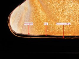
The thickness of the cabin side was 3/4". (Fiberglass hull + filler + inside panel.)
I think what I am going to do is add 1/2" to all the window measurements; that will basically give me 1/4" more all around. That should be enough to clean up any over/under slop in the original cutouts, which are truly very rough.
I didn't pull the windows out of the port side of the boat, just removed the interior trim ring to measure from the inside. I may do one more final check by pulling one of the portside windows before ordering.
Getting closer...
Sven
Seglare
Mark,
I didn't remove our ports but just traced the outline formed by the screws holding them in place. The screws don't go through the glass (wild assumption ) so that outline should be a safe starting point. Like you we'll probably add a small margin just to be safe.
The symmetry port to starboard was surprisingly good so we'll go with the same (mirror) measurements. Your cabin sides seen beefier than ours. When we did the rest of the portholes I'd measured 3/4" but it was actually closer to 1/2".
-Sven
I didn't remove our ports but just traced the outline formed by the screws holding them in place. The screws don't go through the glass (wild assumption
 ) so that outline should be a safe starting point. Like you we'll probably add a small margin just to be safe.
The symmetry port to starboard was surprisingly good so we'll go with the same (mirror) measurements. Your cabin sides seen beefier than ours. When we did the rest of the portholes I'd measured 3/4" but it was actually closer to 1/2".
-Sven
mherrcat
Contributing Partner
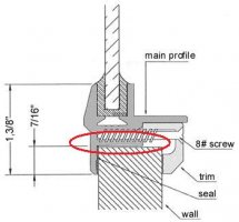
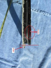
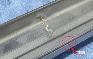
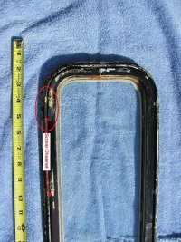
There is actually a small channel that the screw goes into, and about 1/16" of material beyond that to the edge of the extrusion that fits through the cutout.
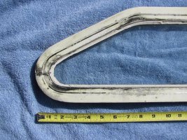
I have attached three pics. The first is of the Bomon extrusion cross section that shows the same principle; the outside edge of the extrusion that goes through the cabin is circled. The next three are pics I took of actual frames that I have from a parted out boat that I have annotated. The first shows the profile of the extrusion, the second shows the channel that the screw goes into and the third shows the outside flange.
Interestingly the exterior face of the Bomon extrusion is 1/4" larger than the original, but the extra 1/4" extends to the glass side of the frame; the flange that fits against the outside of the cabin is actually the same as the original, 7/16" - if the original frame is centered in the cutout.
The only reason I am going to this much trouble is that I want to try to get the new windows to be as close a fit as possible to the cutout without removing a lot of cabin material.
(I just added a 5th pic of the inside of the frame that shows the screw channel better.)
Attachments
Last edited:
mherrcat
Contributing Partner
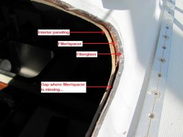
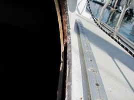
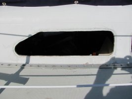
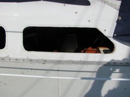
I pulled the two port side windows to measure them and the cutouts. While I was at it I took some picutures.
The first is an angle of the cutout from outside showing the three layers; hull, filler/spacer and interior panelling. (It also shows where the filler is missing along the bottom of the cutout.)
Second is another angle of the same.
Third is exterior of port side forward showing roughness of cutout.
Fourth is exterior of port side aft.
Fifth is of the interior side of the cutout showing how the cutout in the panelling is larger than the cutout in the hull.
I think I have decided to do basically what I mentioned earlier; take each side of the trapezoidal shape, move the line outward 1/4" and use the measurements derived from this larger shape for the new window size. This will let me make all the layers, hull, spacer and panelling flush, which should work better with the Bomon extrusion and trim ring.
I made templates of the larger shapes and they are almost exactly the same as the Bomon port side #1 drawings, except that the part at the top of the angle doesn't extend as far out, which I want it to do.
Attachments
Last edited:

