

Returned to sailing in 2016 after a 20 year absence.
(Continued from Another Engine Panel Upgrade - Pt. 1):
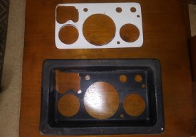
The original black engine panel frame was in pretty good shape. The panel-back has a slight rim around the mounting flange which leaves a shallow void behind the screw holes. I think this is why it often cracks beneath the screws. I filled this void with epoxy around all the screw holes. The black plastic itself is pretty flimsy and the panel was deformed somewhat form having the old gauges clamped against it, but it cleaned up nicely with black spray paint. The thin “nameplate” piece at the bottom (where the switches are labeled) is a separate piece and was probably added, in part, to provide a second layer of thickness and strength to support the switches. I opted for a plastic backing plate for the whole panel-back instead, so I eliminated the nameplate piece--mine was fairly worn and discolored anyway. Also, I had a “breakthrough” moment when trying to figure out a new panel layout—that just flipping the panel upside-down puts the gauges at the bottom (where they are easier to see from the helm) and the switches & cover-plate openings at the top (where they are better shielded from water by the stowage compartment lid). I then used the panel space where the old key-switch had been to make a square-ish cut-out for the Engine-Monitoring Panel, so I moved the key-switch to a mounting plate above the panel where, I could also add a water-resistant USB charger (CHGeek 18W USB Charger Socket, from Amazon $13.89—which includes a built-in voltmeter, on-off switch, and weather-resistant cap).
 .........

I mulled over the choices for a new key-switch. A recent forum post discussed eliminating the key switch altogether and just using an on-off pushbutton. I’m more of a “hang-the-key-from-the-raw-water-seacock” kind of guy so I kept it, but I did opt for a new one. It took PB-Blaster to loosen up the mounting nut from the old switch.
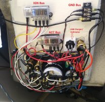
The options for IGN switches are 2-, 3-, or 4-position; allowing various configurations of “BATT,” “IGN,” “START,” and “ACC” (accessory) power. While my original switch was 2 way, I thought it might be slick to use the IGN switch to start the engine (that’s one less wire, one less switch, and 2 fewer ring terminals to troubleshoot during starter problems). And, the ease of online shopping being the mother of all over-thought ideas, I further dreamt-up a use for the “ACC” position so I could convince myself to buy the 4-position switch: I could split the Blue Seas 5046 bus into two, 4-circuit, 5045 busses instead (which also lead to more flexibility in mounting them). The first bus (fed from “ACC”) could power only the items “essential” for engine operation (I decided on glow-plugs, fuel pump, altn excitation + engine monitors, and the water temp gauge). The second bus (powered from “IGN”) would supply non-essential items; all the remaining gauges, all gauge lights, the Hobbs, and any other later desired add-ons (note: “ACC” is also powered when the switch is in “IGN”).
Silly to split up the busses on the starter switch poles? Maybe, but this setup does allow you to run the fuel pump, for example (from “ACC”), without powering buzzers, lights, gauges, and the Hobbs meter (if those are wired to “IGN”). And, individually fused and isolated circuits help greatly when troubleshooting.

I got the panel up and running in time to motor the boat to haulout in late April. I also continued to “trick out” the panel with a few more 5-buck LEDs and lamps from eBay since I was already “in there,” working away. So, the end result is this:
- When the BATT selector at the Nav Station is turned to BATT 1 or BATT 2, power is available to the engine-panel key-switch, the blower can be powered thru the blower switch, and the USB charger can be turned on, which also displays the Voltage supplied to the engine panel.
- When the key switch is set to “ACC,” the fuel pump ticks, the engine low oil pressure light and silence-able buzzer (on the Engine Monitor Panel) are active, power is available to the glow-plug switch and the water temp gauge, and a Blue LED panel light illuminates to indicate that the “ACC” bus is powered. No blue light, and none of the above should operate. A blue light but any non-functioning component means an individual component fuse has likely blown. Additionally, a Red Lamp next to the glow-plug switch illuminates while the glow-plug switch is depressed (this is accompanied by a drop on the voltmeter, an audible change in the ticking of the fuel pump, and a “lower” glow of the warning lamps while the glow plugs are being powered). No illumination of the red lamp while “glow” is depressed means the glow-plug fuse is blown. A glow of the red lamp but none of the accompanying indications means a problem with the individual glow plug(s).
- When the key is turned to “IGN,” all the “ACC” components continue to be powered while the remaining gauges, all gauge lights, the Hobbs, and the original low-oil pressure light and (non-silence-able) buzzer become powered.
- When the key is turned to START, power is briefly removed from the “ACC” bus and the starter engages. All the panel components are repowered when the key is returned to the “IGN” position (i.e., the normal configuration while the engine is running).
Final Installation Notes:
1. In the end, I’m going to keep the old push-button start switch in addition to the key-start switch. That’s because in “START” on the key switch, the “IGN” post is powered, but not the “ACC” post. So, on a cold-start day, if you want to hold the glow-plugs during start (or, keep the fuel pump running during multiple cranking attempts) you’d need the original circuitry which powered all three circuits (start, glow, and fuel pump) simultaneously. In my case, this can be done by wiring the old pushbutton start switch to the ACC bus.
2. I’m going to run a new 12ga wire [white] from the “ACC” bus back to the engine bay. This wire will feed its own Blue-Seas 5045 bus in the engine bay, powering:
3. The old “purple” wire for alternator excitation will be re-purposed as the (+) return from the new Oil Pressure sensor to the Engine Monitoring Panel. I’ll run new wires for the (+) return for the Manifold Temp warning light (green) and the Oil pressure gauge (blue), as well as adding an oil pressure sender to a previous installed oil pressure “manifold”.
So, a little work left to do, but the guts are in place and working properly. Nice to hear the engine crank over heartily and roar to life like I've never heard it do before.
(See Part III - https://ericsonyachts.org/ie/ubs/another-engine-panel-upgrade-pt-3.723/)
The original black engine panel frame was in pretty good shape. The panel-back has a slight rim around the mounting flange which leaves a shallow void behind the screw holes. I think this is why it often cracks beneath the screws. I filled this void with epoxy around all the screw holes. The black plastic itself is pretty flimsy and the panel was deformed somewhat form having the old gauges clamped against it, but it cleaned up nicely with black spray paint. The thin “nameplate” piece at the bottom (where the switches are labeled) is a separate piece and was probably added, in part, to provide a second layer of thickness and strength to support the switches. I opted for a plastic backing plate for the whole panel-back instead, so I eliminated the nameplate piece--mine was fairly worn and discolored anyway. Also, I had a “breakthrough” moment when trying to figure out a new panel layout—that just flipping the panel upside-down puts the gauges at the bottom (where they are easier to see from the helm) and the switches & cover-plate openings at the top (where they are better shielded from water by the stowage compartment lid). I then used the panel space where the old key-switch had been to make a square-ish cut-out for the Engine-Monitoring Panel, so I moved the key-switch to a mounting plate above the panel where, I could also add a water-resistant USB charger (CHGeek 18W USB Charger Socket,
from Amazon $13.89—which includes a built-in voltmeter, on-off switch, and weather-resistant cap).
I mulled over the choices for a new key-switch. A recent forum post discussed eliminating the key switch altogether and just using an on-off pushbutton. I’m more of a “hang-the-key-from-the-raw-water-seacock” kind of guy so I kept it, but I did opt for a new one. It took PB-Blaster to loosen up the mounting nut from the old switch.
The options for IGN switches are 2-, 3-, or 4-position; allowing various configurations of “BATT,” “IGN,” “START,” and “ACC” (accessory) power. While my original switch was 2 way, I thought it might be slick to use the IGN switch to start the engine (that’s one less wire, one less switch, and 2 fewer ring terminals to troubleshoot during starter problems). And, the ease of online shopping being the mother of all over-thought ideas, I further dreamt-up a use for the “ACC” position so I could convince myself to buy the 4-position switch: I could split the Blue Seas 5046 bus into two, 4-circuit, 5045 busses instead (which also lead to more flexibility in mounting them). The first bus (fed from “ACC”) could power only the items “essential” for engine operation (I decided on glow-plugs, fuel pump, altn excitation + engine monitors, and the water temp gauge). The second bus (powered from “IGN”) would supply non-essential items; all the remaining gauges, all gauge lights, the Hobbs, and any other later desired add-ons (note: “ACC” is also powered when the switch is in “IGN”).
Silly to split up the busses on the starter switch poles? Maybe, but this setup does allow you to run the fuel pump, for example (from “ACC”), without powering buzzers, lights, gauges, and the Hobbs meter (if those are wired to “IGN”). And, individually fused and isolated circuits help greatly when troubleshooting.
I got the panel up and running in time to motor the boat to haulout in late April. I also continued to “trick out” the panel with a few more 5-buck LEDs and lamps from eBay since I was already “in there,” working away. So, the end result is this:
- When the BATT selector at the Nav Station is turned to BATT 1 or BATT 2, power is available to the engine-panel key-switch, the blower can be powered thru the blower switch, and the USB charger can be turned on, which also displays the Voltage supplied to the engine panel.
- When the key switch is set to “ACC,” the fuel pump ticks, the engine low oil pressure light and silence-able buzzer (on the Engine Monitor Panel) are active, power is available to the glow-plug switch and the water temp gauge, and a Blue LED panel light illuminates to indicate that the “ACC” bus is powered. No blue light, and none of the above should operate. A blue light but any non-functioning component means an individual component fuse has likely blown. Additionally, a Red Lamp next to the glow-plug switch illuminates while the glow-plug switch is depressed (this is accompanied by a drop on the voltmeter, an audible change in the ticking of the fuel pump, and a “lower” glow of the warning lamps while the glow plugs are being powered). No illumination of the red lamp while “glow” is depressed means the glow-plug fuse is blown. A glow of the red lamp but none of the accompanying indications means a problem with the individual glow plug(s).
- When the key is turned to “IGN,” all the “ACC” components continue to be powered while the remaining gauges, all gauge lights, the Hobbs, and the original low-oil pressure light and (non-silence-able) buzzer become powered.
- When the key is turned to START, power is briefly removed from the “ACC” bus and the starter engages. All the panel components are repowered when the key is returned to the “IGN” position (i.e., the normal configuration while the engine is running).
Final Installation Notes:
1. In the end, I’m going to keep the old push-button start switch in addition to the key-start switch. That’s because in “START” on the key switch, the “IGN” post is powered, but not the “ACC” post. So, on a cold-start day, if you want to hold the glow-plugs during start (or, keep the fuel pump running during multiple cranking attempts) you’d need the original circuitry which powered all three circuits (start, glow, and fuel pump) simultaneously. In my case, this can be done by wiring the old pushbutton start switch to the ACC bus.
2. I’m going to run a new 12ga wire [white] from the “ACC” bus back to the engine bay. This wire will feed its own Blue-Seas 5045 bus in the engine bay, powering:
1. Fuel Pump
2. Alternator Excitation
3. Oil Pressure and Manifold Temperature sensors for the Engine Monitoring Panel
4. Any future “key-switch” powered devices
3. The old “purple” wire for alternator excitation will be re-purposed as the (+) return from the new Oil Pressure sensor to the Engine Monitoring Panel. I’ll run new wires for the (+) return for the Manifold Temp warning light (green) and the Oil pressure gauge (blue), as well as adding an oil pressure sender to a previous installed oil pressure “manifold”.
So, a little work left to do, but the guts are in place and working properly. Nice to hear the engine crank over heartily and roar to life like I've never heard it do before.
(See Part III - https://ericsonyachts.org/ie/ubs/another-engine-panel-upgrade-pt-3.723/)
-
 23178.jpg
 -
 23180.jpg

