HELP!- Wiring Issues

Kenneth K

1985 32-3, Puget Sound
Blogs Author
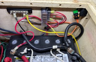
In the tech’s defense I think what you see draped over the battery negative is Jeff’s drawing showing the connection between the orange wire and the red coming off the battery.
Yeah, after another look, I think you're right about that. That is a little better...
 
Last edited:

Prairie Schooner

Jeff & Donna, E35-3 purchased 7/21
Good idea on placement and I wonder why it wasn’t done that way. What would give the tech the idea to go back and forth across all that space instead of making the cleanest line between the two ends?

In the tech’s defense I think what you see draped over the battery negative is Jeff’s drawing showing the connection between the orange wire and the red coming off the battery. It’s too long and it’s unsecured, but I think it runs behind the battery and not over the top of it.

Somebody I know with a lifetime of experience on boats recently said he’s never finished a project without immediately realizing he could have done something differently and better :)

battery wiring 2024_4 b.jpg
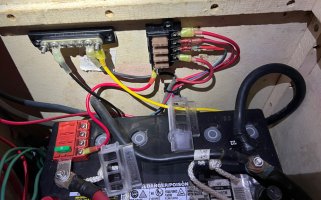
Chris &/or Jim, you're correct. Here's another shot with that wire lifted up so it's fully visible, no photo editing. It's a 30a fuse. He has it set up so the clear case on the fuse block traps the wire. Maybe his attempt to keep it off the battery. That seems a little janky to me.
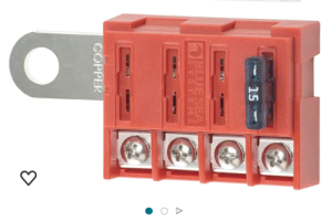
I'm going to get one of those battery mount units Ken highlighted.
 

Kenneth K

1985 32-3, Puget Sound
Blogs Author
I think Blue Sea says the capacity of these is 100A total, and 30A max per fuse, so you should be fine with a 30A fuse protecting the 4 x 5A fuse block.

Screenshot_20240415-182142.png

I actually use mine with a 40A fuse one the 30A shore power charger circuit to the battery. But I keep the total fused amperage well below 100A so I think this is a forgivable crime.
 

southofvictor

Member III
Blogs Author
Nice! Only thing I’d ask is there a way to keep the positive wire from bearing on the negative battery cable? Maybe an anchor on the bulkhead giving it a little direction to keep it clear? Or if not tie them together so they couldn’t chafe?
 

Prairie Schooner

Jeff & Donna, E35-3 purchased 7/21
Make sure you use proper tinned wire and heat shrink terminals.

Here is a schematic I came up with for my panel replacement project (Universal Diesel engine). Note the fuel sender wire doesn't match up to the fuel gauge, its an old diagram and I can't find the new one.
View attachment 43244
And some photos of the final project here:


Some resources that might be helpful:

Wire and fuse chart: https://d2pyqm2yd3fw2i.cloudfront.net/files/resources/reference/20010.pdf
Lots of technical help: https://www.bluesea.com/support/reference
Source for wire: https://www.boatwireusa.com/
Source for terminals: https://shop.sailboatowners.com/search.php?brand=sailboat&kw=FTZ
How to install terminals: https://marinehowto.com/marine-wire-termination/

Good luck with the project.

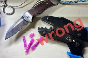
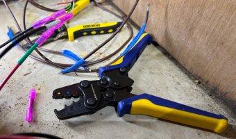
Thanks for posting these. The link from Marine How To helped me realize I was using a tool all wrong. When I started electric projects a few years ago I anted up for a ‘double crimp ratchet tool’. I thought it was to crimp both sides of a two wire connector in one operation. It didn’t do that well and I had to flip the tool and crimp a second time because it only seemed to do one side well. This was awkward and still didn’t result in a reliably solid crimp.
splicing 6164 X sm.jpg

I got so frustrated while trying to crimp wires for the new LPG controls that I was tempted to solder joints. (another discussion, I don’t think that’s as dire as ABYC makes it to be) I watched a video on crimping and decided to buy a 'crimping tool for heat shrink connectors'. It’s worked beautifully. Then I went back and read the MHT article and discovered why the first one wasn't 'working'.
splicing 6185 sm.jpg

I decided to put this here in case there were other electric neophytes who would find it useful. You don’t know what you don’t know.
 

Loren Beach

O34 - Portland, OR
Senior Moderator
Blogs Author
I decided to put this here in case there were other electric neophytes who would find it useful. You don’t know what you don’t know.
Looking at the picture but not seeing what I should be seeing. Is there an explanation of how to use the crimp tool correctly?
 

Prairie Schooner

Jeff & Donna, E35-3 purchased 7/21
Looking at the picture but not seeing what I should be seeing. Is there an explanation of how to use the crimp tool correctly?
Thanks for pointing that out, Loren. I should rewrite it. They're different tools. The MHT article will explain the difference better than I can.
 
Last edited:

shard7

1974 E27 'Bluey'
Looking at the picture but not seeing what I should be seeing. Is there an explanation of how to use the crimp tool correctly?
Yes, the different types of crimp connectors need specific crimp tools (or different dies in the same tool). A tool designed for regular 'insulated' connectors will do a terrible job on heat shrink connectors and vice versa.


Loren Beach

O34 - Portland, OR
Senior Moderator
Blogs Author
Thanks! I am probably over thinking the whole thing. That said I have had a crimp that I "thought" was fine, pull apart when I gave it a yank before installation. I do have a crimp tool very similar to the one in the link.
 

southofvictor

Member III
Blogs Author
Ancor makes double crimpers for non heat shrink terminals and single crimpers for heat shrink ones. I think the idea is that the second crimp on the non heat shrink ones crimps the longer insulated housing to the wire insulation. This isn’t necessary in a heat shrink terminal since the heat shrink does a better job of the same thing. The crimp at the terminal end of the terminal should be enough to mechanically fasten the terminal to the wire by itself. Personally I like using the double crimpers and adding my own heat shrink over a standard terminal although I’m starting to see the value in the time savings of heat shrink terminals.
 

southofvictor

Member III
Blogs Author
A former shipmate (and electrical engineer) still insisted on soldering everything and adding two heat shrinks, one about 1/4” longer than the other. I’ve heard soldering actually makes a hard spot that can cause premature failure, so I use that as an excuse not to solder as long as I can avoid it
 

Prairie Schooner

Jeff & Donna, E35-3 purchased 7/21
. . . I’ve heard soldering actually makes a hard spot that can cause premature failure, so I use that as an excuse not to solder as long as I can avoid it
I understand that's the ABYC line. But solder is made from a lot of tin (compositions vary), which doesn't work harden easily. And the typical joint isn't active all the time like bending a paper clip, which is what would be necessary to work harden and break. The soldering probably doesn't introduce enough heat to anneal the joint, but I don't think it hardens it. The crimping of a joint introduces some work hardening to the wire which would make it (slightly) more susceptible to breaking.
A solder joint is solid metal with full conductivity. Sounds like many of us have crimps we don't have 100% confidence in. I'll probably continue to crimp. But when I put the bow pulpit back on, with new LED bow light, I soldered those joints. It was too hard to get to to fix if it was a bad crimp.
 

Solarken

Member III
I have an 1973 Ericson E-32. We have been experiencing issues with wiring. Apparently someone miswired the ignition control panel and it keeps shorting out. Most recently I think it toasted the starter. Can anyone: 1) Steer me to a schematic that I can make sense of...or draw one perhaps. 2) Take a photo of the inside of your E-32 panel. 3) Provide me with a schematic of the engine wiring so it can be made right. According to a local wrench the coil is mis-wired, the panel is mis-wired, etc.

DESPERATE!!!
I have an 1973 Ericson E-32. We have been experiencing issues with wiring. Apparently someone miswired the ignition control panel and it keeps shorting out. Most recently I think it toasted the starter. Can anyone: 1) Steer me to a schematic that I can make sense of...or draw one perhaps. 2) Take a photo of the inside of your E-32 panel. 3) Provide me with a schematic of the engine wiring so it can be made right. According to a local wrench the coil is mis-wired, the panel is mis-wired, etc.

DESPERATE!!!
I have a 1975 32-2. The full wiring is shown in the boats manual. Hoping you have the one for your boat.
 

Prairie Schooner

Jeff & Donna, E35-3 purchased 7/21
engine panel Aqualarm 77 sm.jpeg
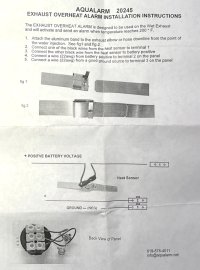
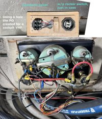
I'm installing an Aqualarm as part of the coolant/exhaust system rebuild. It looks like I just need a positive and a negative in addition to the wires from the sensor. Can I wire what I need from the engine control panel? Since it only needs to be energized when the engine is running, can I pull what I need off the key switch?

engine panel 2025_5 plan 1.jpg
. . . . (composite photo)

I've been going through the following threads trying to wrap my head around it.
- https://ericsonyachts.org/ie/ubs/another-engine-panel-upgrade-pt-2.702/?page=2#ubs-comment-4137
- https://ericsonyachts.org/ie/ubs/going-overboard-with-the-engine-instrument-panel.896/
- https://ericsonyachts.org/ie/ubs/new-engine-panel-fabrication-part-iii.611/
- https://ericsonyachts.org/ie/threads/dummy-check-my-engine-panel-wiring.17954/

As long as I'm making that top panel, I'm putting in a waterproof rocker switch. Maybe for the blower if I decide to put one back in.

One of these years I'll do a complete wiring upgrade. For now I just want to add things we need in a way that might play nice with that, someday.

Any help would be greatly appreciated.
Jeff
 
Last edited:

Angel D.

Member III
Hello Jeff !

I would think there is no problem to power that sensor from the key . If the manufacturer suggests 22awg. Cables Very little current is required for the sensor ,That's my logic.
 

Kenneth K

1985 32-3, Puget Sound
Blogs Author
Since it only needs to be energized when the engine is running, can I pull what I need off the key switch?
Yes, that's the right idea--to power it off of the "switched" side of the key switch.
The simplest way would be to to just add another ring terminal to the "switched" side of the key switch, leading to the aqualarm panel.
The next level would be to mount a small bus or terminal strip next to the engine panel. Power this bus strip with a lead from the key switch. Then you could wire the aqualarm panel, the blower switch, and any add-on equipment to the new bus panel.
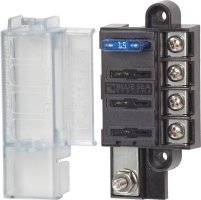
The next level above that might be to add a fused bus strip next to the engine panel and wire your new components to that. Then, every new circuit you add on to the engine panel (via the key switch) is fuse protected so any shorts on your added circuits won't take out the whole engine panel.
5045.jpg

Also, for your heat sensor itself, you'll need a (+) source to power the sensor down in the engine compartment. While the instructions say "+ POSITIVE BATTERY VOLTAGE," I think it's silly to hook this up to an "always hot" battery source--it only needs to be powered when the engine panel is powered. Which sounds like it leads you back to your key switch, except that Ericson has already provided a "switched" circuit that runs back to the engine compartment. It's the alternator excitation/fuel pump wire.

So, in the short run, I'd say you could wire the (+) side of the temp sensor to the (+) supply line for the fuel pump. That way, it becomes energized only when the key is on.

But, in the long run (at least on my boat) there was a pre-existing problem with the fuel pump wiring: Rather than running two "key-switched" (+) lines from the engine panel to the engine compartment (one for alternator excitation, and one for the fuel pump), they only ran one. And the one they ran was the purple, 16 ga wire that was originally meant just for the alternator. So, I had the fuel, pump, the Hobbs meter, and alternator excitation all powered by a small 16 ga wire. This is why I mention, in part 2 of my engine panel blog, "running a new 12ga [10ga] wire from the “ACC” bus [engine panel] back to the engine bay."

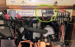
In the end, I replaced the purple 16 ga wire to the engine compartment with a 10ga wire leading to a fused bus panel. This panel powers the fuel pump, alternator excitation, the Hobbs, and my engine temp/oil pressure sensors, each with its own circuit protection (green circle, below).
20200412_181252~3.jpg
 
Last edited:

Prairie Schooner

Jeff & Donna, E35-3 purchased 7/21
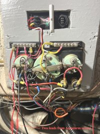
This is what I did, just using parts on hand. The boat's not in the water and I haven't connected the batteries yet.
- If I don't have the right color/gauge wire, I use the gauge I want and wrap each end with the right color tape (covered with clear heat shrink). New circuits installed get a unique number which I'm keeping a log of.

engine panel 2025_5-29 81.JPG

If you get a minute, I'd welcome any observations. Will I burn the boat down?
 
Top